Downflow valve of water tank in toilet sealed up by rotary startstop ceramic ring in mode

A technology of rotary opening and closing, ceramic ring, applied in flushing equipment with water tanks, water supply devices, buildings, etc., can solve the problems of easy water leakage, short life, high force and so on

Inactive Publication Date: 2004-10-27
浙江帅博卫浴科技有限公司
View PDF0 Cites 4 Cited by
  • Summary
  • Abstract
  • Description
  • Claims
  • Application Information

AI Technical Summary

Problems solved by technology

This method is prone to water leakage, short

Method used


Image

  • Downflow valve of water tank in toilet sealed up by rotary startstop ceramic ring in mode
  • Downflow valve of water tank in toilet sealed up by rotary startstop ceramic ring in mode
  • Downflow valve of water tank in toilet sealed up by rotary startstop ceramic ring in mode

Examples


Embodiment Construction

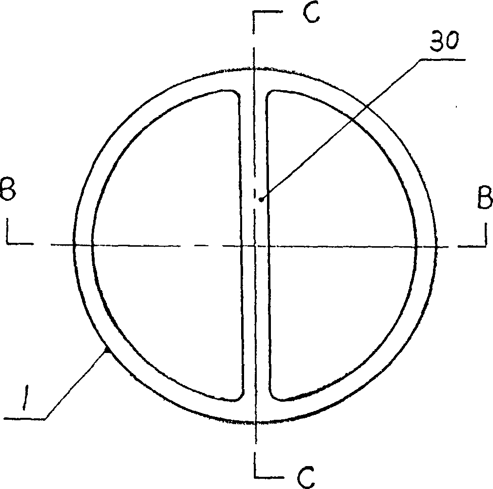
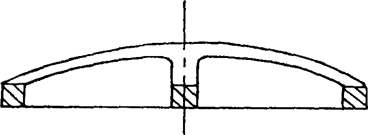
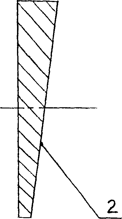
[0013] The working principle and working conditions of the present invention will be described in detail below with reference to the drawings.

[0014] The ceramic ring 1 has a rib 30 on its diameter. The top of the ceramic ring 1 is cut along the rib 30 into a bevel, and the bevel is ground and polished as the sealing surface 2. Take two ceramic rings 1, one of which is called static ring 3. Its bottom 4 is installed on the plastic base 24 above the round drain 5 of the drain valve. The other is called the moving ring 6, and its bottom 4 is mounted on the open end 8 of the plastic dome 7 with a certain depth 33. The installation method of this embodiment is: the bottom 4 of the stationary ring 3 and the base 24 and the bottom 4 of the moving ring 6 and the open end 8 of the dome 7 are glued together to ensure that the joint does not leak water. An arm 9 extends from the dome 7 and is sleeved on the inclined shaft 10 of the base 24. The inclined shaft 10 is perpendicular to the se...


PUM


Abstract

A drain valve for the toilet cistern features that shear rotation between the sealing surfaces of moving and static ceramic rings is used to open or close it. Its advantages are no leakage, long service life and small opening force.

Description

Technical field [0001] The invention is a toilet water tank drain valve that is opened and closed by a shearing rotation method and sealed with a ceramic ring. Background technique [0002] The traditional toilet water tank straight-down valve adopts rubber seal. This method is prone to water leakage, has a short life, and requires a lot of force when opening. Summary of the invention [0003] The object of the present invention is to provide a method of shearing and rotating the sealing surface of the ceramic moving ring relative to the sealing surface of the ceramic static ring to realize the opening and closing of the drain valve. Since the ceramic sealing surface can be polished flat and smooth, when the two sealing surfaces overlap and the drain valve is closed, the water pressure in the water tank is used to close the cover so that it does not leak, and the opening is labor-saving and has a long life. [0004] The present invention...

Claims


Application Information

Patent Timeline
IPC IPC(8): E03D1/34
Inventor 马宏威
Owner 浙江帅博卫浴科技有限公司
Why Eureka
Try Eureka