
Method and device for managing power source of electronic equipment

A technology of power management device and electronic device, which is applied in the direction of data processing power supply, etc., and can solve problems such as the inability to meet the requirements of power saving

Inactive Publication Date: 2004-10-27
WISTRON NEWEB
View PDF3 Cites 3 Cited by
  • Summary
  • Abstract
  • Description
  • Claims
  • Application Information

AI Technical Summary

Problems solved by technology

[0004] However, these designs still cannot meet the requirements of power saving, and more power saving power management methods and devices are needed.

Method used

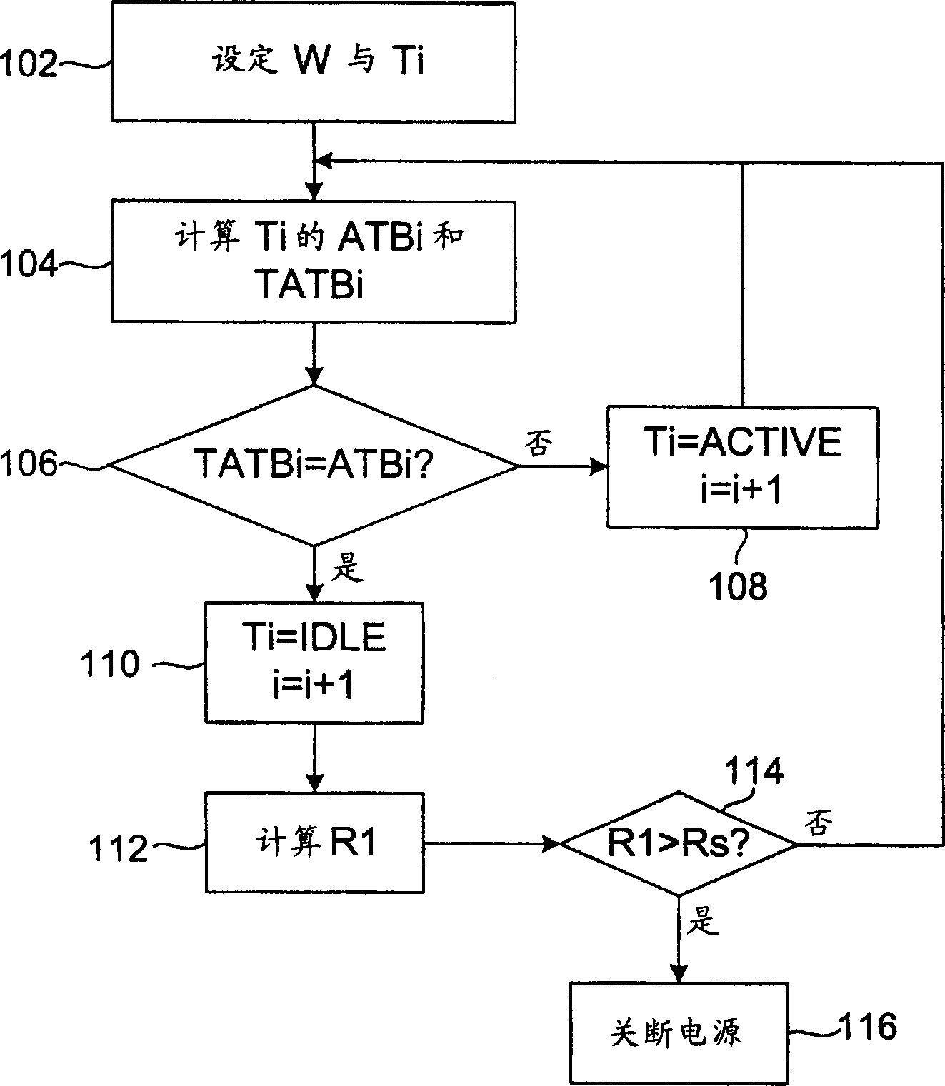
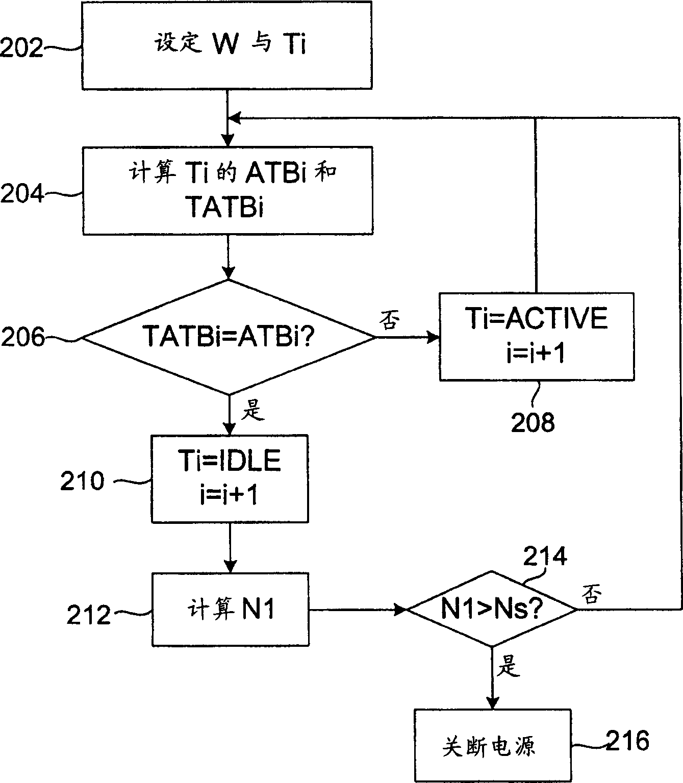
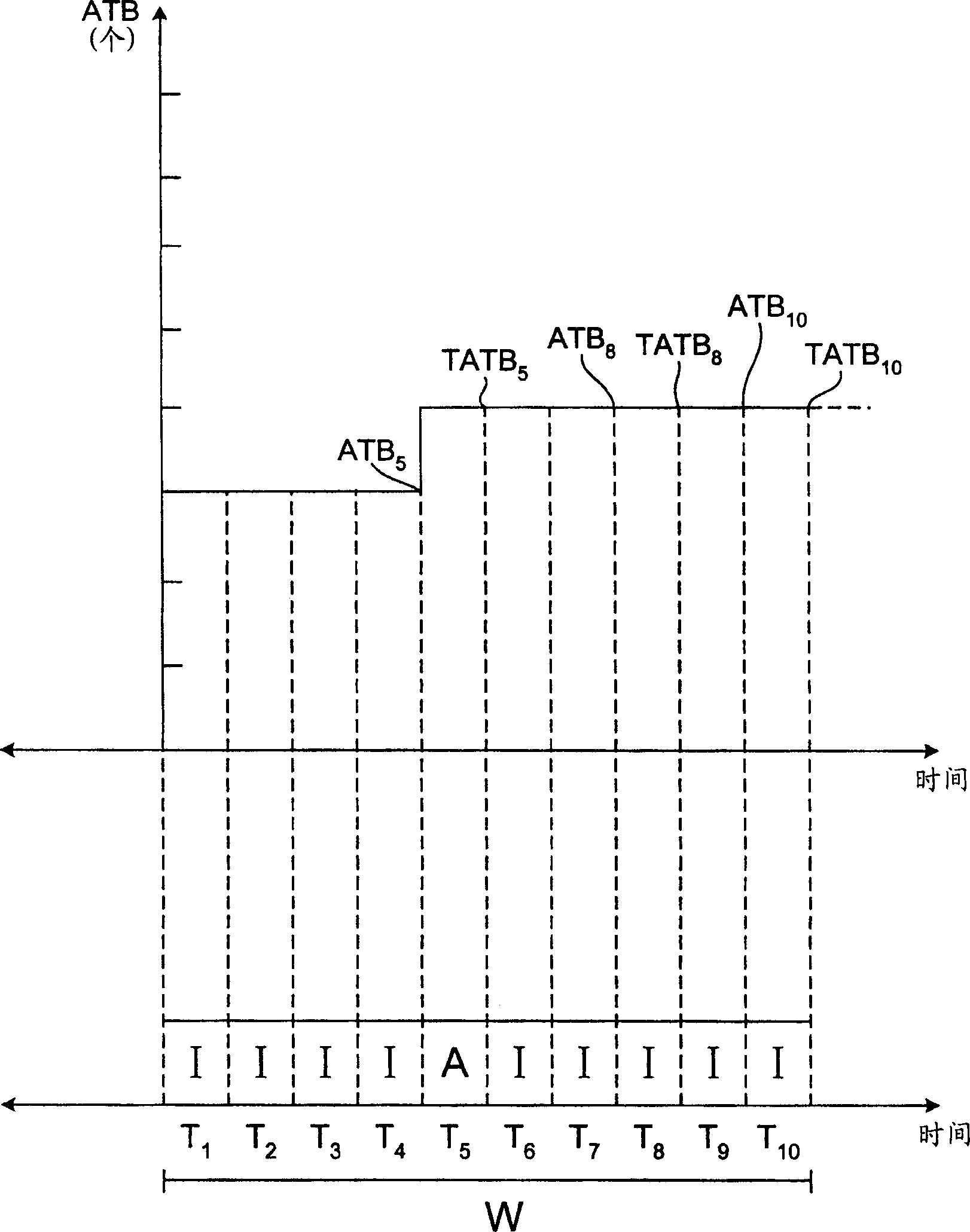

Image

  • Method and device for managing power source of electronic equipment
  • Method and device for managing power source of electronic equipment
  • Method and device for managing power source of electronic equipment

Examples


Embodiment Construction

[0036] The invention provides a power management method and device for an electronic device. The electronic device has first and second power modes, and its operating state can be divided into first and second operating states.

[0037] The first embodiment of the power management method

[0038] first reference figure 1 and image 3The first embodiment of the power management method in the present invention will be described. In this embodiment, the first power mode is off, and the second power mode is on. In this case, the electronic device is initially in the second power mode. In addition, the first operating state is idle, and the second operating state is working.

[0039] First, a sampling time interval W is set, and the sampling time interval W includes a plurality of sampling unit times Ti (step 102 ). The sampling time interval W can be set by the user, in this embodiment it is 10 minutes. The length of the sampling unit time Ti can be any value, and it is 1 mi...


PUM


Abstract

The device possesses first and second power modes, and operation states can be divided to first and second operation states. The method includes steps: setting up a sampling time interval, and the sampling time interval includes multiple sampling unit times; based on operations of the device in each sampling unit time, determining operation state in each sampling unit time; in the sampling time interval, calculating ratio of first operation state in sampling unit time; based on the said ratio, determining power mode; if the ratio larger than a preset value, controlling the device in first power mode; if the ratio less than a preset value, controlling the device in second power mode.

Description

technical field [0001] The invention relates to a power management method and device for an electronic device. Background technique [0002] Mobile electronic devices that can access wireless networks are growing in popularity. However, the power consumption in current wireless network devices is still high, which is a burden for mobile electronic devices using batteries. [0003] For example, US Patent Nos. US 6,330,462 B1, US 6,236,674 B1, US 6,489,725 B1, etc. all propose methods for managing power supplies of electronic devices. The communication system of US 6,330,462 B1 manages power by changing the data transmission rate, and the system includes a transmitter and a receiver. Its management method includes the following steps. Initially run the transmitter at idle rate. Then receive the data to be transmitted at a high rate. A high rate notification is then sent to the receiver. Data is finally sent out at this high rate. US 6,236,674 B1 manages the power supply...

Claims


Application Information

Patent Timeline
IPC IPC(8): G06F1/32
Inventor 周良光邱陵
Owner WISTRON NEWEB
Learn More