Closed rotary compressor

A rotary compressor, a closed-type technology, used in rotary piston machinery, rotary piston pumps, mechanical equipment, etc., can solve problems such as compressor vibration, low compression efficiency, and overall compressor imbalance, to prevent vibration. , the effect of improving the compression efficiency

Inactive Publication Date: 2004-11-24
LG ELECTRONICS (TIANJIN) APPLIANCES CO LTD
View PDF0 Cites 12 Cited by
  • Summary
  • Abstract
  • Description
  • Claims
  • Application Information

AI Technical Summary

Problems solved by technology

[0012] However, the existing hermetic rotary compressor has a problem that since the suction hole 71 and the discharge hole 72 are respectively formed at the positions close to the two sides of the vane receiving groove 73, there is a problem with the suction and discharge action. The suction and discharge forces of the cyli

Method used


Image

  • Closed rotary compressor
  • Closed rotary compressor
  • Closed rotary compressor

Examples


Example Embodiment

[0039] Hereinafter, the structure and operation process of the hermetic rotary compressor of the present invention will be described in detail with reference to the accompanying drawings.
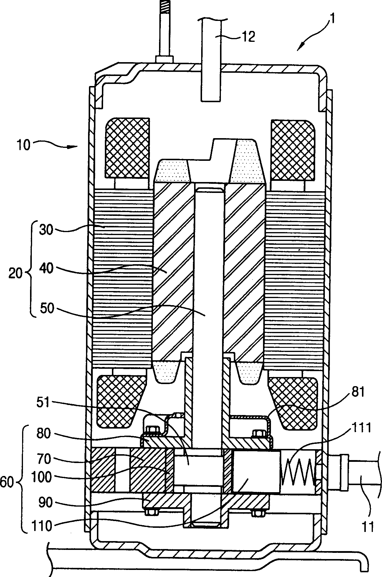
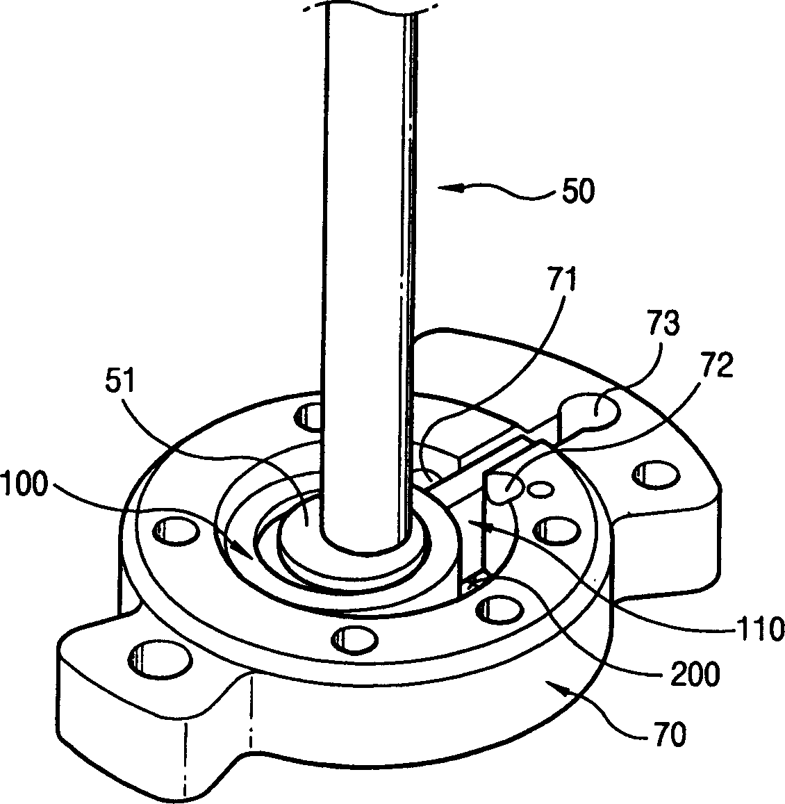
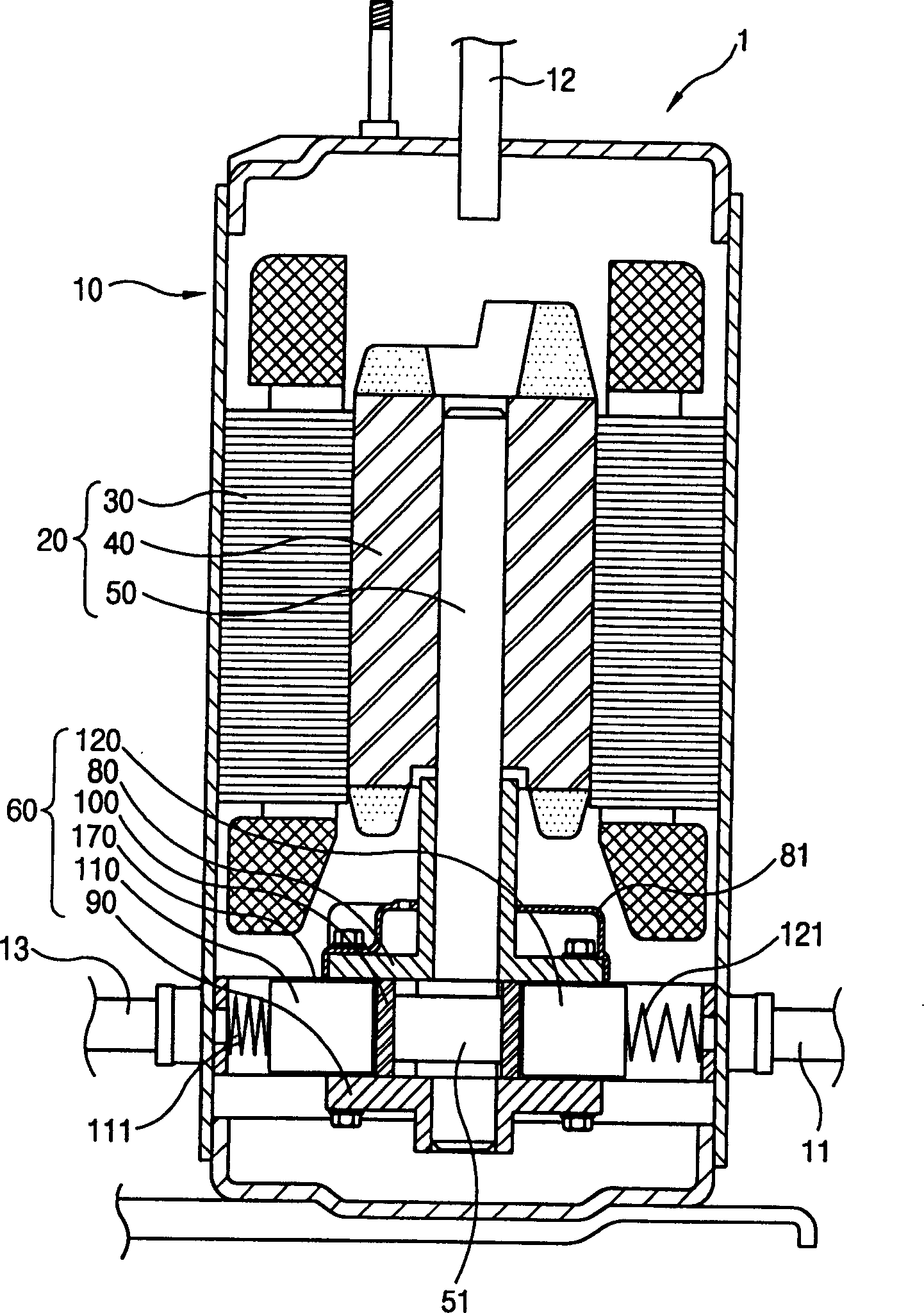
[0040] Figure 3 to Figure 9 It is a diagram of a hermetic rotary compressor adopting an embodiment of the present invention, in which image 3 Is a longitudinal section view of a closed rotary compressor, Figure 4 To show the side view of the operating state of the hermetic rotary compressor, Figure 5 Is the side view of the cylinder, Figure 6 In order to show a plan view of the compression state of the first compression chamber of the cylinder, Figure 7 for Figure 6 The graph of the action state, Figure 8 In order to show a plan view of the compression state of the second compression chamber of the cylinder, Picture 9 for Figure 8 The graph of the state of action.

[0041] As shown in the figure, in an embodiment of the enclosed rotary compressor of the present invention, an electric ...


PUM


Abstract

The sealed rotary compressor includes the following parts: cylinder assembly; rotating shaft installed to penetrate the cylinder assembly and to form eccentric part; rotating piston moving together with the eccentric part of the rotating shaft and capable of rotating and revolving inside the sealed space; and several vanes with one end contacting with the rotating piston, inserted into the cylinder body to reciprocate linearly in radius direction, and separating the sealed space to compress the refrigerant sucked via the sucking holes and exhaust via the exhaust holes. Each turn of the rotating shaft can realize several strokes and this raises the compression efficiency. The sucking force and the exhaust force produced with the compression of the refrigerant are symmetrical about the cylinder axle, and this can prevent vibration of the compressor caused by unbalance.

Description

technical field [0001] The present invention relates to a hermetic rotary compressor (HERMETIC ROTARY COMPRESSOR), more precisely, the present invention relates to a hermetic rotary compressor with the following functions: it can form several cylinders inside the cylinder for cooling the refrigerant Inhale, compress and then discharge the processed compression space, so that the compression efficiency can be improved, and the vibration can also be reduced by balancing. Background technique [0002] Hereinafter, a conventional hermetic rotary compressor will be described with reference to the drawings. figure 1 It is a longitudinal sectional view of an existing hermetic rotary compressor, figure 2 It is a side view showing the operating state of a conventional hermetic rotary compressor. [0003] As shown in the figure, in the existing hermetic rotary compressor 1, an electric structural component 20 is provided at the upper end of the interior of the airtight container 10...

Claims


Application Information

Patent Timeline
IPC IPC(8): F04C18/356
Inventor 赵镛庚
Owner LG ELECTRONICS (TIANJIN) APPLIANCES CO LTD
Why Eureka
Try Eureka