Method for joining of structural members by friction plug welding

A technology for structural components and structural assemblies, applied in welding equipment, welding/welding/cutting items, non-electric welding equipment, etc., can solve problems such as rivet consumption, reduction of component fatigue strength, and mutual interference in the process of forming auxiliary welding joints

Inactive Publication Date: 2005-01-12
THE BOEING CO
View PDF1 Cites 15 Cited by
  • Summary
  • Abstract
  • Description
  • Claims
  • Application Information

AI Technical Summary

Problems solved by technology

Rivets can also interfere with the process of forming secondary welded joints along joint interfaces between structural components
In particular, rivets are unlikely to be completely consumed in welded joints, which leads to stress concentrations in the resulting structural components that reduce the fatigue strength of the components

Method used


Image

  • Method for joining of structural members by friction plug welding
  • Method for joining of structural members by friction plug welding
  • Method for joining of structural members by friction plug welding

Examples


Embodiment Construction

[0026] The present invention will be described more fully hereinafter with reference to the accompanying drawings, which show preferred and representative embodiments of the invention. This invention may, however, be embodied in many different ways and should not be construed as limited to these embodiments; rather, these embodiments are provided so that this disclosure will be thorough, and will fully convey the scope of the invention to those skilled in the art . In the drawings, the same reference numerals denote the same elements.

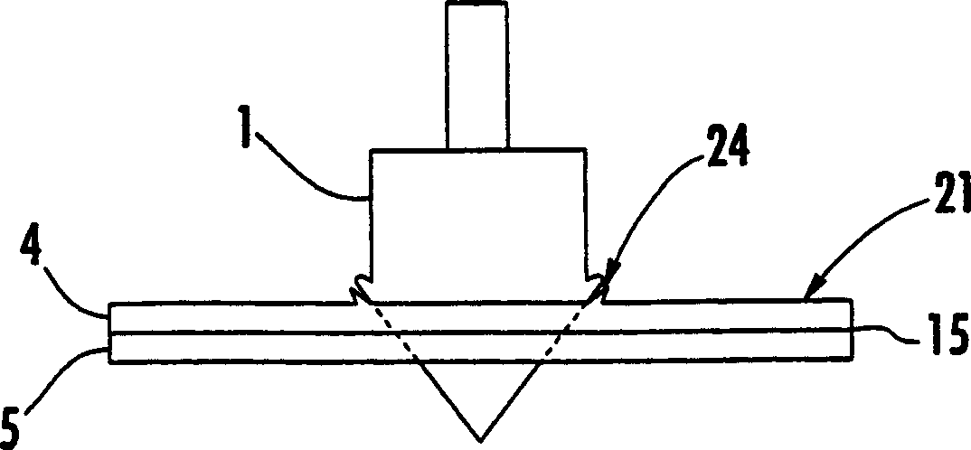
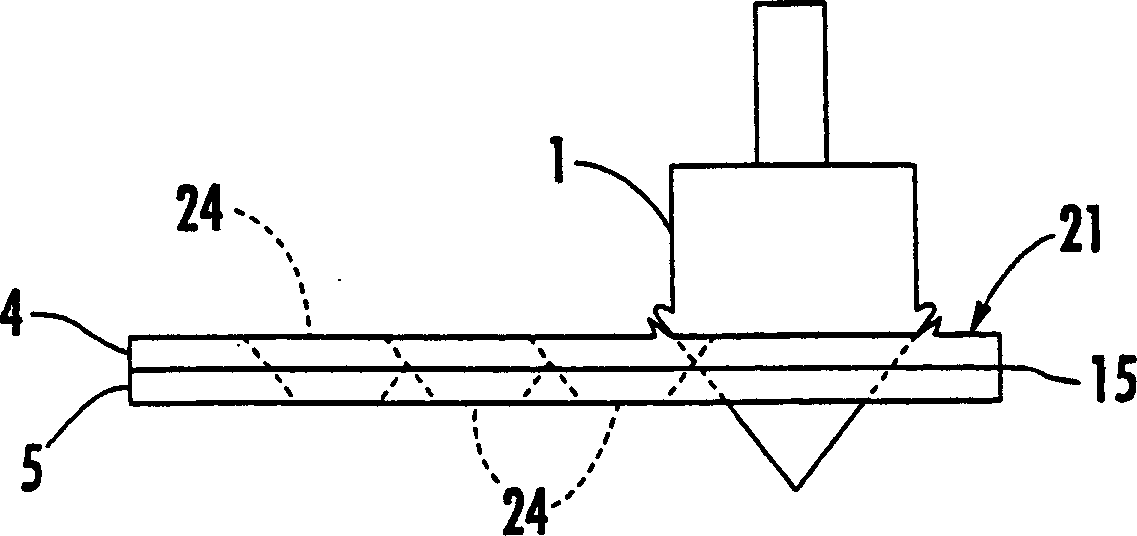
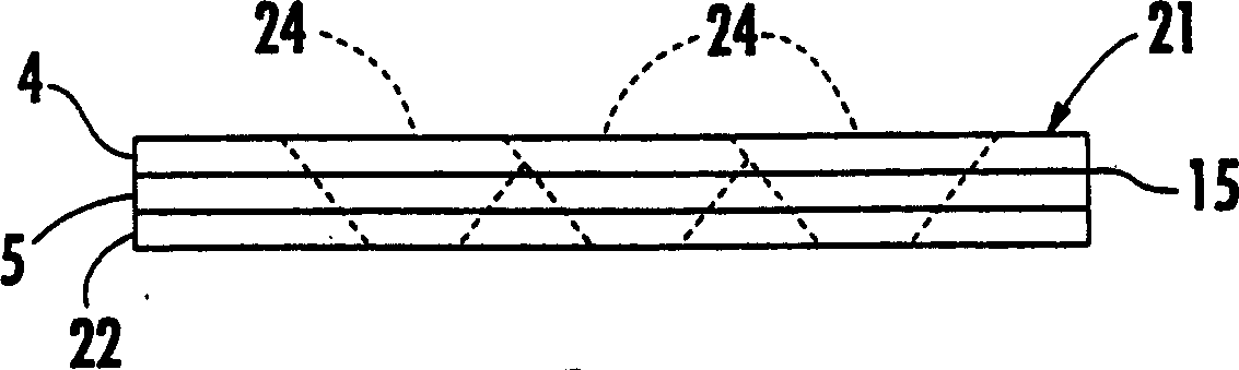
[0027] Referring below to the accompanying drawings, in particular figure 1 , which shows a structural assembly 21 according to an embodiment of the present invention. The structural assembly 21 comprises a friction plug weld 24 connecting the first and second structural parts 4, 5 together. refer to figure 2 , which shows a plug 1 for forming a friction plug weld 24 according to one embodiment of the present invention. The plug 1 can hav...


PUM


Abstract

The method of manufacturing a structural assembly includes positioning a first structural member at least partially adjacent a second structural member to define an interface therebetween and inserting a rotating plug into the first and second structural members at the interface to thereby join the first structural member to the second structural member. The resulting friction plug weld provides a relatively strong joint between the structural members, requires less forming and machining time, and is compatible with single-sided tooling. Additionally, the friction plug weld is compatible with other joining methods, such as friction stir welding.

Description

technical field [0001] The present invention relates to friction welding, and more particularly to methods of joining structural components by friction plug welding. Background technique [0002] Structural assemblies, such as those in the aerospace industry, are often constructed by joining structural components together. The structural components may be connected to each other by welding along joint interfaces between the components or by using fasteners such as rivets, screws or bolts. Often, structural components with complex geometries or configurations need to be joined, which complicates the joining process. For example, when joining structural components with curved shapes, it can be difficult to position and secure the components to each other while preventing gaps and keeping the joint interface clear. Also, certain structural components have shapes that restrict access to joint interfaces between components. For example, when attaching a dome member to a column...

Claims


Application Information

Patent Timeline
Patent Type & Authority Applications(China)
IPC IPC(8): B23K20/12B23K103/10B23K103/14
CPCB23K20/1295B23K20/12B23K20/129B23K20/122
Inventor 道格拉斯J·沃尔德伦雷蒙德·米尔叶克塔基思R·麦克特南
Owner THE BOEING CO
Why Eureka
Try Eureka