Radar device capable of scanning received reflection waves

A technology of radar devices and reflected waves, applied to measurement devices, radio wave reflection/re-radiation, and utilization of re-radiation, etc., can solve problems such as insufficient miniaturization

Inactive Publication Date: 2005-02-02
FUJITSU GENERAL LTD
View PDF2 Cites 12 Cited by
  • Summary
  • Abstract
  • Description
  • Claims
  • Application Information

AI Technical Summary

Problems solved by technology

Therefore, even if the number of antennas is reduced according to the above-mentioned radar device, it is still insufficient in terms of miniaturization.

Method used


Image

  • Radar device capable of scanning received reflection waves
  • Radar device capable of scanning received reflection waves
  • Radar device capable of scanning received reflection waves

Examples


Embodiment Construction

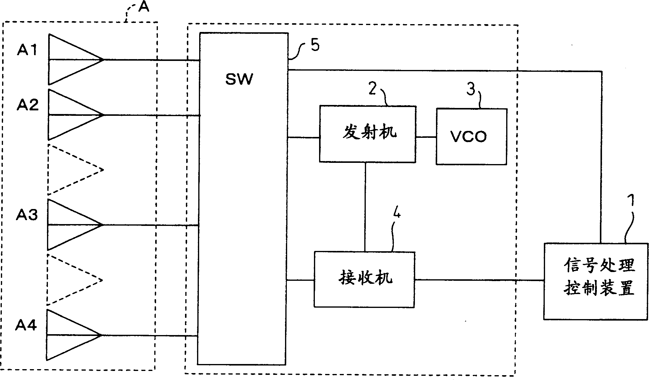
[0042] In order to clarify the effects of the present invention, first, the structure of a conventional radar device that does not apply the present invention and receives and scans reflected waves of radio waves transmitted by digital multi-beam forming (DBF) will be specifically described.

[0043] Thus, in Figure 12 A schematic block structure of the radar device is shown in . In this radar device, the three transmitting antennas of A1, A2, and A3, and the receiving antennas of A4 and A5 are connected to a switching unit 5, and a voltage-controlled oscillator outputting a high-frequency signal in the 76 GHz band, for example, is connected to the switching unit 5. Transmitter 2 and receiver 4 of oscillator 3 (VCO). The receiver 4 synchronizes with the oscillating signal from the oscillator 3 , and transmits the received signal from the receiving antenna to the signal processing control device 1 . Furthermore, the signal processing control device 1 performs digital multi-b...


PUM


Abstract

The present invention relates to a radar device for forming multi-beams in multiple channels from reflected waves of a transmitted wave by using a minimum number of antennas. The device has: antennas used for both transmission and reception A1 - A4; transmission / reception switching means (5) of each antenna; a transmitter (2); and a receiver (4) for receiving the reflected waves of the transmitted wave. The ratio of the distance between adjacent antennas A1 and A2 to the distance between adjacent antennas A2 and A3 or A3 and A4 is 1:2. The transmitted signal is transmitted from each of the antennas selected sequentially and the received signal is processed by digital beamforming (DBF) in a signal processing controller (1), wherein eleven channels can be implemented by using four antennas and a space for six antennas.

Description

technical field [0001] The present invention relates to a radar device using frequency-modulated continuous wave transmission waves (FM-CW), and more particularly to a radar device for receiving and scanning reflected waves related to transmitted radio waves by digital multi-beam forming (DBF). Background technique [0002] Conventionally, various radar devices that perform reception scanning using DBF have been known and developed. In general, the basic structure of such a radar device is to prepare a transmitting antenna and a plurality of receiving antennas, transmit radio waves from the transmitting antenna, and receive reflected waves related to the transmitted radio waves with the plurality of receiving antennas. [0003] However, in the radar device of this configuration, the number of receivers corresponding to the number of receiving antennas is required, and a plurality of receivers must be provided in order to improve scanning accuracy. Therefore, there is a prob...

Claims


Application Information

Patent Timeline
Patent Type & Authority Applications(China)
IPC IPC(8): G01S7/02G01S7/03G01S13/34G01S13/93H01Q3/24H01Q3/26H04B7/06H04B7/08
CPCH04B7/0874H04B7/0691H04B7/0604H01Q3/24G01S13/426G01S13/345G01S7/03H01Q23/00H01Q3/26G01S7/034H04B7/0805H04B7/0822
Inventor 伊佐治修
Owner FUJITSU GENERAL LTD
Why Eureka
Try Eureka