Infrared communication equipment utilizing reflecting device

A technology of infrared communication and reflection device, applied in electrical components, electromagnetic wave transmission systems, transmission systems, etc., can solve the problems that signal processing equipment cannot achieve infrared communication, equipment cannot perform infrared communication, and the installation space is small.

Inactive Publication Date: 2005-02-02
LG ELECTRONICS (CHINA) R&D CENT CO LTD
View PDF0 Cites 5 Cited by
  • Summary
  • Abstract
  • Description
  • Claims
  • Application Information

AI Technical Summary

Problems solved by technology

[0008] This kind of infrared module has such a problem. Due to the characteristics of infrared communication, the infrared module must be installed within 30 degrees in front of the communication department. If this condition is not met, the above-mentioned equipment cannot perform infrared communication.
[0009] For example, when the installation space is narrow and the signal processing devices have to be installed at positions beyond the above-mentioned angle range, infrared communication cannot be realized between the signal processing devices
[0010] In particular, recently, the infrared modules used in the above-mentioned infrared communication devices have been standardized, manufactured in the form of chips and widely used, but the problem remains that the respective installed infrared modules must be positioned within the above-mentioned angular range.

Method used


Image

  • Infrared communication equipment utilizing reflecting device
  • Infrared communication equipment utilizing reflecting device
  • Infrared communication equipment utilizing reflecting device

Examples


Embodiment Construction

[0020] Beneficial embodiments of the present invention will be described in detail below with reference to the accompanying drawings.

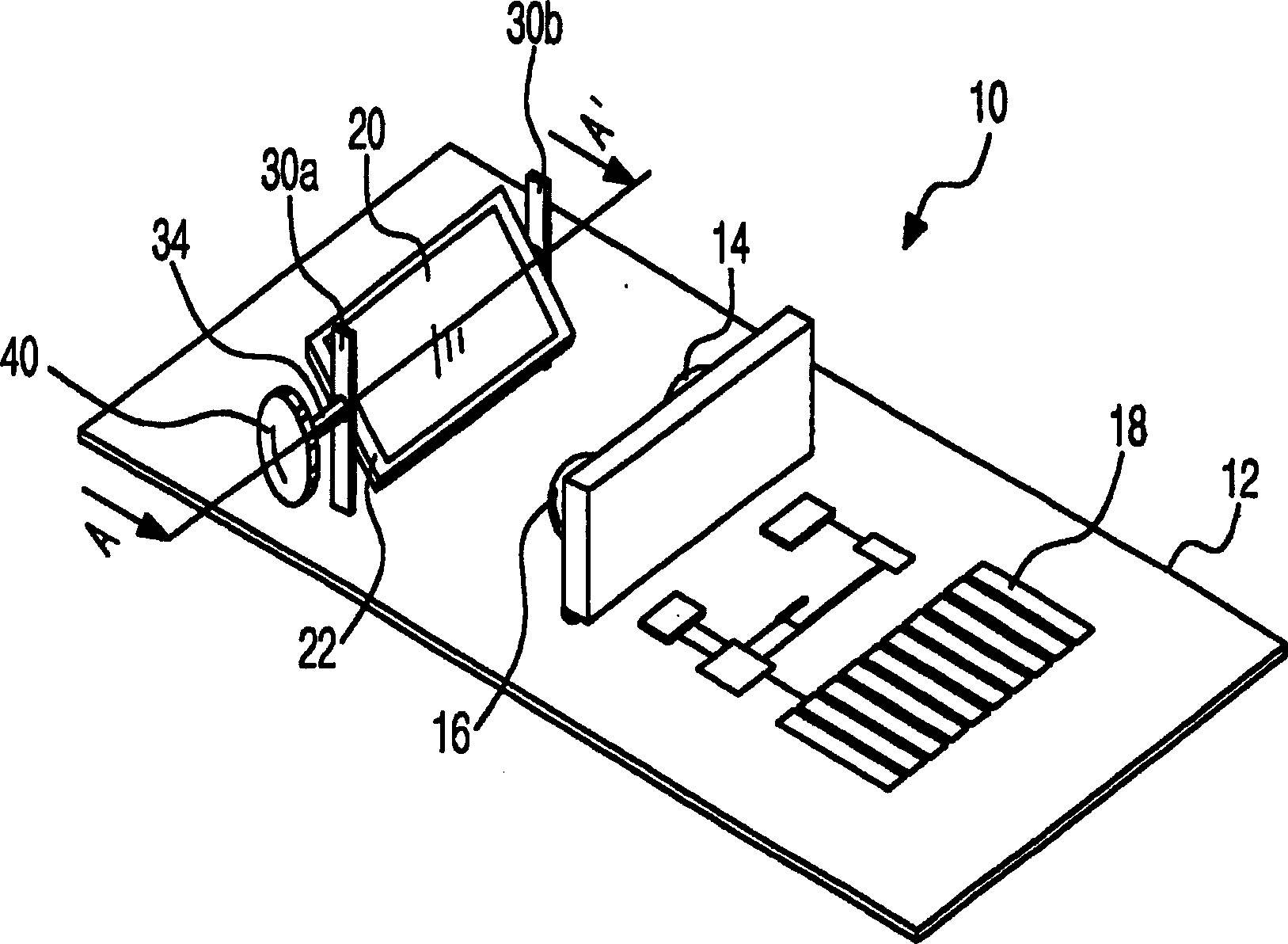
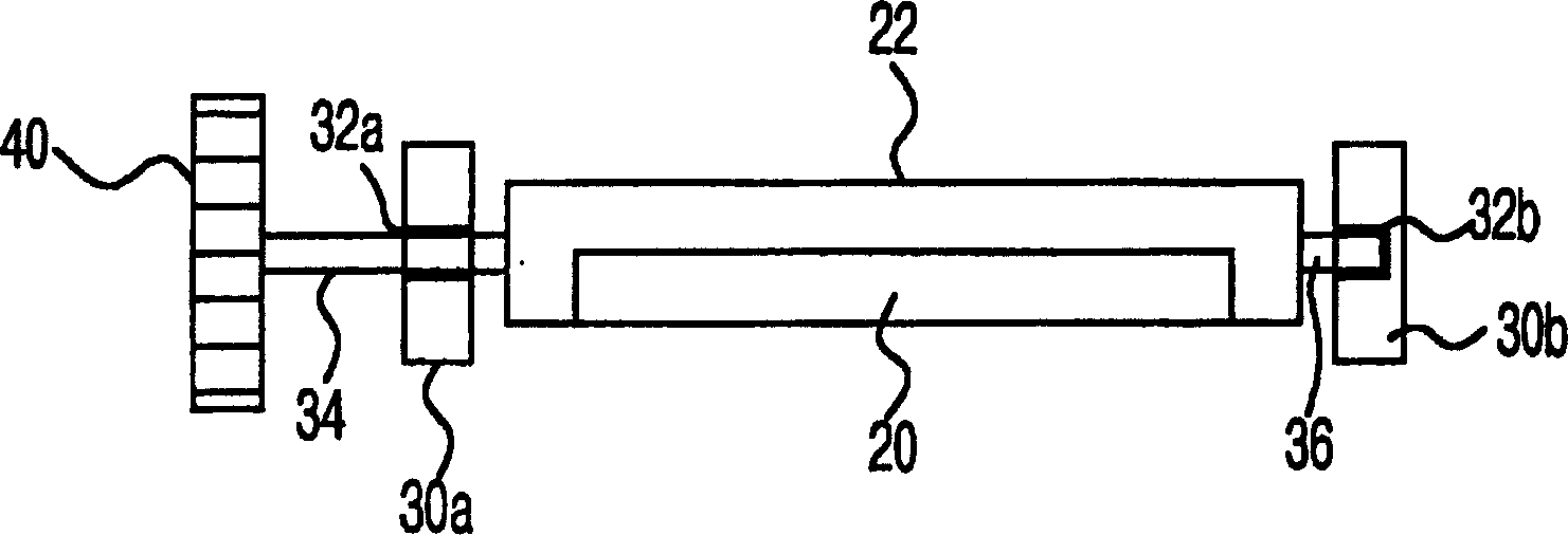
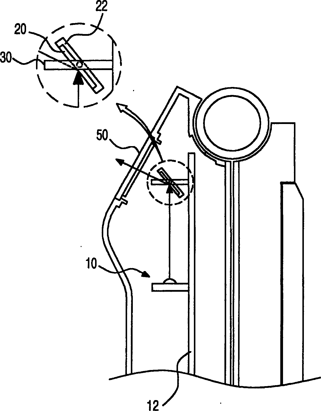
[0021] First refer to Figure 1 to Figure 4 , illustrating the structure of an infrared communication device using a reflection device according to an embodiment of the present invention, figure 1 is a schematic diagram of an infrared communication device module utilizing a reflection device according to an embodiment of the present invention, figure 2 yes figure 1 A cross-sectional view of A-A` of the infrared communication device shown, image 3 It is a cross-sectional view of a state in which an infrared communication device using a reflector is mounted on a mobile communication terminal, Figure 4 It is an external view of a state in which an infrared communication device using a reflector is mounted on a mobile communication terminal.

[0022] Figure 1 to Figure 4 The shown infrared communication equipment using a reflection devi...


PUM


Abstract

The invention relates to an infrared communication device which uses the reflection unit, comprising the following parts: a reflection unit, which can reflect the infrared rays received or emitted by the receiving part and emitting part and change the direction of the received and emitted infrared rays; a rotating wheel, which provides rotary force for the reflection unit to drive the reflection unit to rotate and to receive and emit the infrared rays on the required directions. In the invention, if the user rotates the wheel in the positive and negative directions, the rotating shaft rotates and the reflecting mirror rotates along with the rotation of the rotating shaft, so as to easily receive and emit the signal with the infrared communication device on other direction or at the outside. Moreover, in the structure that the infrared emitting and receiving device is required to have a random angle, the user can utilize the reflection unit and the rotating wheel to adjust the required angle easily, so that the installation and design can be done freely and free from the position limitation of the design form and circuit design to the infrared modules.

Description

technical field [0001] The present invention relates to an infrared communication device, in particular to an infrared communication device utilizing a reflection device. It has a reflection device on one side of an infrared module capable of one-to-one sending and receiving. By adjusting the reflection angle of the reflection device, it is easy to Send and receive signals with infrared communication devices located in other directions or outside. Background technique [0002] Generally speaking, an infrared communication device is a device that can transmit data through infrared rays without using a data line between a computer or a mobile communication terminal and a peripheral device, and mainly performs one-to-one communication. [0003] This kind of infrared communication equipment is a special form of wireless transmission equipment, which can modulate the concentrated light in the infrared spectrum measured in trillion hertz or trillion hertz into information, and sen...

Claims


Application Information

Patent Timeline
Patent Type & Authority Applications(China)
IPC IPC(8): H04B1/38H04B10/11
CPCH04B1/3827H04B10/11
Inventor 韩相浩
Owner LG ELECTRONICS (CHINA) R&D CENT CO LTD
Why Eureka
Try Eureka