Optical disk drive tray withdraw control method

A control method and a tray technology, which are applied in the directions of recording information storage, instruments, etc., can solve the problems such as the falling of the optical disc 30, the inability of the tray 20 to overcome the magnetic attraction force, and the inability to hold the optical disc 30.

Inactive Publication Date: 2005-02-16
LITE ON TECH CORP
View PDF0 Cites 1 Cited by
  • Summary
  • Abstract
  • Description
  • Claims
  • Application Information

AI Technical Summary

Problems solved by technology

However, when the optical drive is placed vertically and the tray 20 places the optical disc 30, the vibration of the tray will cause the protruding part 25 of the tray 20 to have no way to support the optical disc 30, causing the optical disc 30 to fall when the optical drive is ejected.
[0008] If the ejection force given to the tray 20 decreases, it may be impossible for the tray 20 to overcome the magnetic attraction force and the entire tray 20 cannot be successfully ejected.

Method used


Image

  • Optical disk drive tray withdraw control method
  • Optical disk drive tray withdraw control method
  • Optical disk drive tray withdraw control method

Examples


Embodiment Construction

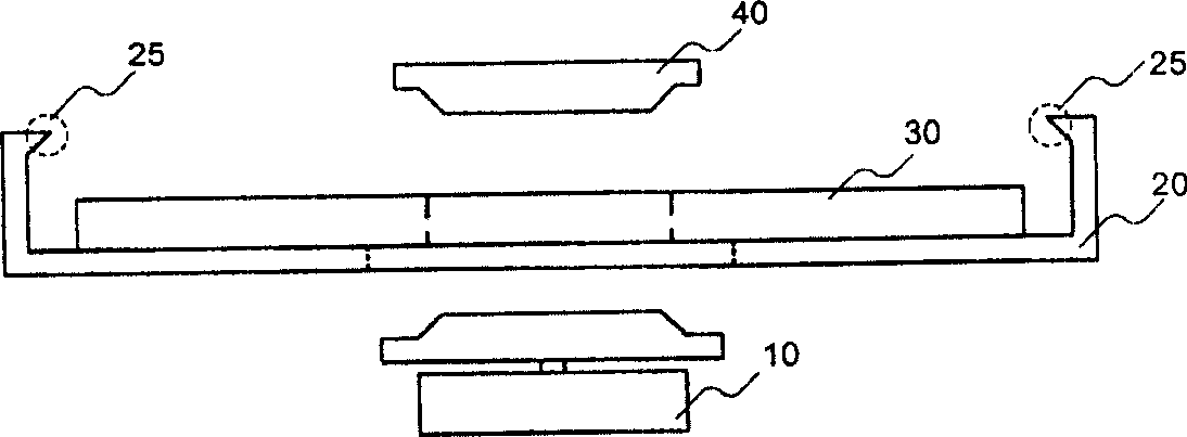
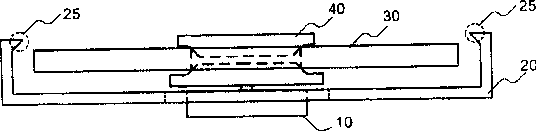
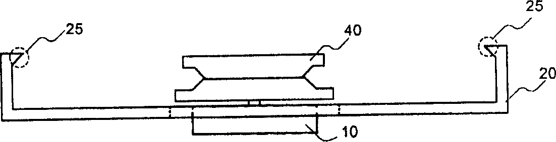
[0020] The present invention is an improvement on the situation that the optical disc 30 falls when the known vertically placed optical drive is unloaded. Please refer to Figure 2a and Figure 2b , which shows the waveform diagram of the ejection force of the tray of the optical drive of the present invention. Among them, the voltage (V) value represents the force applied to the pallet, and the higher the voltage, the greater the force.

[0021] Such as Figure 2a As shown in , it shows the tray ejection force waveform when an optical disc is placed in the optical drive of the present invention. When the optical drive places a disc and executes the eject operation, such as Figure 2a As shown, the exit force voltage of 6V is provided within the initial 20ms, and then the voltage of the exit force is changed to 3.4V until 200ms. The dotted line I displayed at 200ms means that the position of the tray is no longer affected by the attractive force of the permanent magnet at...


PUM


Abstract

When optical disk is placed to tray, first functional force is applied to tray optical drive to overcome a lesser magnetic attraction, when optical disk is not placed to tray, second functional force is applied to tray optical drive to overcome a larger magnetic attraction. Maximum of second functional force is larger than maximum of first functional force.

Description

technical field [0001] The invention relates to a method for controlling the ejection of a tray of an optical drive, in particular to a method capable of controlling the ejection force of the tray according to whether an optical disc is placed in the optical drive. Background technique [0002] Please refer to Figure 1a , which shows a schematic diagram of the spindle motor, tray, and clamping device in the optical drive. The positions of the components in the optical drive are, from bottom to top, the spindle motor 10 , the tray 20 , and the clamping device 40 . The tray 20 can be used to place the optical disc 30, and there are several tabs 25 on the tray 20. When the optical drive is placed vertically, the tabs 25 can hold the optical disc 30 so that the optical disc 30 will not fall out of the tray. 20. [0003] Please refer to Figure 1b , when the disc is placed on the tray 20 and after the tray is placed (Tray In), the spindle motor 10 will rise and prop up the di...

Claims


Application Information

Patent Timeline
Patent Type & Authority Applications(China)
IPC IPC(8): G11B17/04
Inventor 许振榕李宜忠
Owner LITE ON TECH CORP
Why Eureka
Try Eureka