
Universal vernier positioning instrument

A locator and vernier technology, which is applied in the direction of the center gun, the drilling mold for the workpiece, the workshop equipment, etc., can solve the problems of high cost, difficulty in scribing on the flat platform of the workpiece, and difficulty in scribing the plane of the large workpiece.

Inactive Publication Date: 2005-03-02
孙世梁
View PDF0 Cites 9 Cited by
  • Summary
  • Abstract
  • Description
  • Claims
  • Application Information

AI Technical Summary

Problems solved by technology

[0002] It is difficult to draw lines on the traditional workpiece plane platform, which requires relatively strong technical skills, and it is more difficult to draw lines on large workpieces;
[0003] Using the current special drilling mold to drill holes, if the batch of workpieces is small, the cost will be too high

Method used


Image

  • Universal vernier positioning instrument

Examples


Embodiment Construction

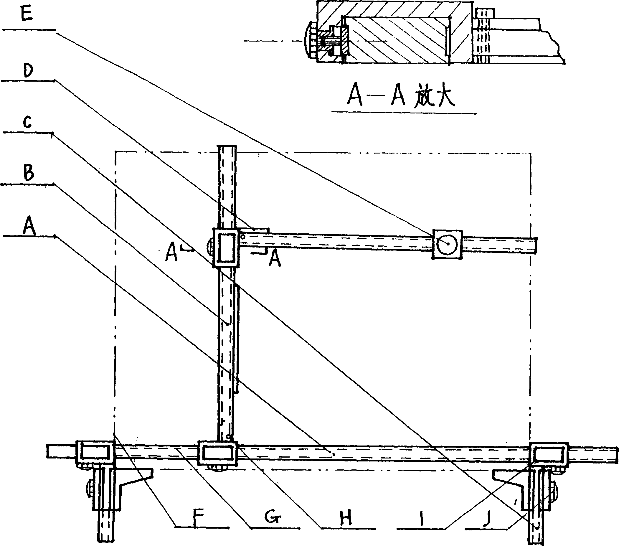
[0020] To complete points, circles, holes, and lines on the workpiece, the steps are:

[0021] 1. Position the reference rod——

[0022] After the reference rod is placed flat on the workpiece plane to determine the position, it is locked with a magnetic base (suitable for large workpiece planes). Or place the reference rod flat on the workpiece plane, use the reference adjustment rod to find the correct position of the reference rod, and tighten the knob, lock it with a magnetic base, so that the reference rod and the workpiece plane are firmly combined.

[0023] 2. Splicing the moving rod to reach the desired position——

[0024] (1) Clamp the groove of the moving rod on the reference rod, then the moving rod can move laterally on the reference rod;

[0025] (2) Clip the groove of the second moving rod on the first moving rod. The second moving rod can move longitudinally along the first moving rod. In this way, the first and second moving rods can move vertically and hori...


PUM


Abstract

The universal vernier positioning instrument as one important scribing tool in machine manufacture may be used to replace traditional scribing platform and drilling mold with difficulty in scribing large workpiece. The instrument is simple in operation, precise, efficient and multipurpose. It may be used in scribing point, circle, hole and line via fixing datum rod on some workpiece plane, clamping the notch of the movable rod onto the datum rod and assembling one other movable rod for determining position in transverse and longitudinal displacement. It may be used to scribe directly on workpiece plane, and its steel eye may be used in direct positioning, drilling hole and scribing circle. Wherein, magnetic catch may be used for fixing.

Description

technical field [0001] The technical invention is a common tool for scribing lines in industrial and mechanical manufacturing industries. Background technique [0002] It is difficult to draw lines on the traditional workpiece plane platform, which requires relatively strong technical skills, and it is more difficult to draw lines on large workpieces; [0003] If the current special-purpose drilling mold is used to drill holes, if the batch of workpieces is small, the cost will be too high. Contents of the invention [0004] Use the reference rod of the instrument to place it flat on the workpiece plane to confirm the position, use the groove of the moving rod to clamp on the reference rod, and splice with the moving rod so that it can move vertically and horizontally, and accurately find points, drill holes, Draw straight lines and circle lines on centerless pieces. [0005] The steel eye on the moving rod can be directly drilled (the steel eye can be replaced) instead ...

Claims


Application Information

Patent Timeline
Patent Type & Authority Applications(China)
IPC IPC(8): B23B47/28B25D5/00B25H7/04
Inventor 孙世梁
Owner 孙世梁
Learn More