Low section high gain vertical polarized omnidirectional antenna

A vertically polarized, omnidirectional antenna technology, applied to antennas, antenna arrays, antenna arrays that are individually powered, etc., can solve the problems of low gain, large space and inconvenient installation.

Inactive Publication Date: 2005-03-02
SHANGHAI JIAO TONG UNIV
View PDF0 Cites 8 Cited by
  • Summary
  • Abstract
  • Description
  • Claims
  • Application Information

AI Technical Summary

Problems solved by technology

[0004] The purpose of the present invention is to overcome the deficiencies and defects existing in the prior art, to provide a low-profile high-gain vertically polarized omnidirectional antenna, which solves the common problem in the vertically polarized digital TV mobile reception in the prior art Tie-rod antennas are used, which have low gain and take up a large space. Some use large antenna arrays, especially to increase the gain height or even reach several wavelengths. The installation is inconvenient and unsightly, and even affects the safety of mobile carriers.

Method used


Image

  • Low section high gain vertical polarized omnidirectional antenna
  • Low section high gain vertical polarized omnidirectional antenna

Examples


Embodiment Construction

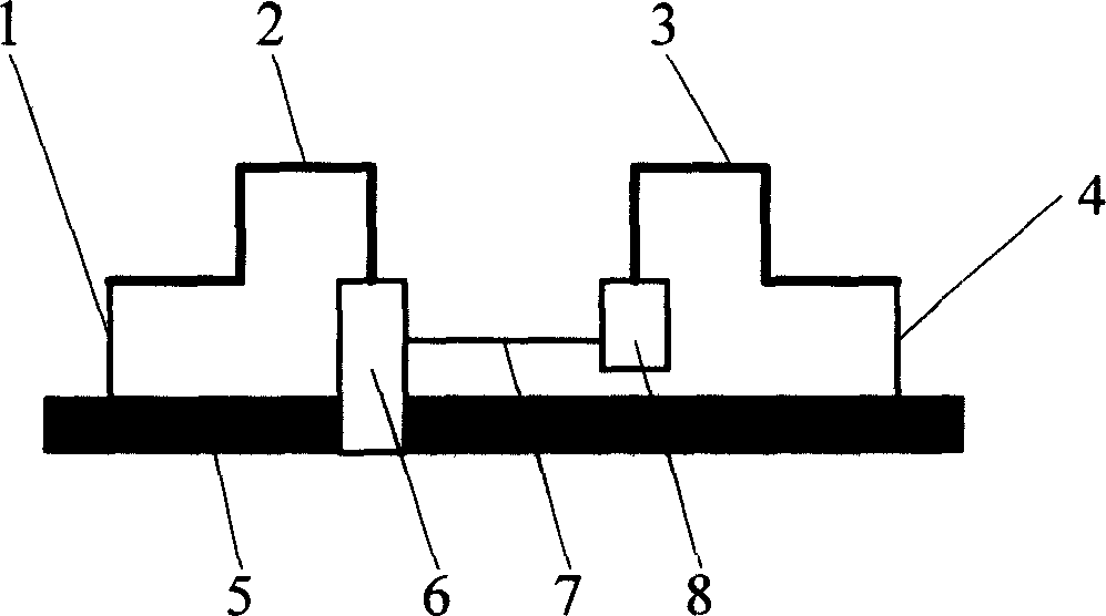
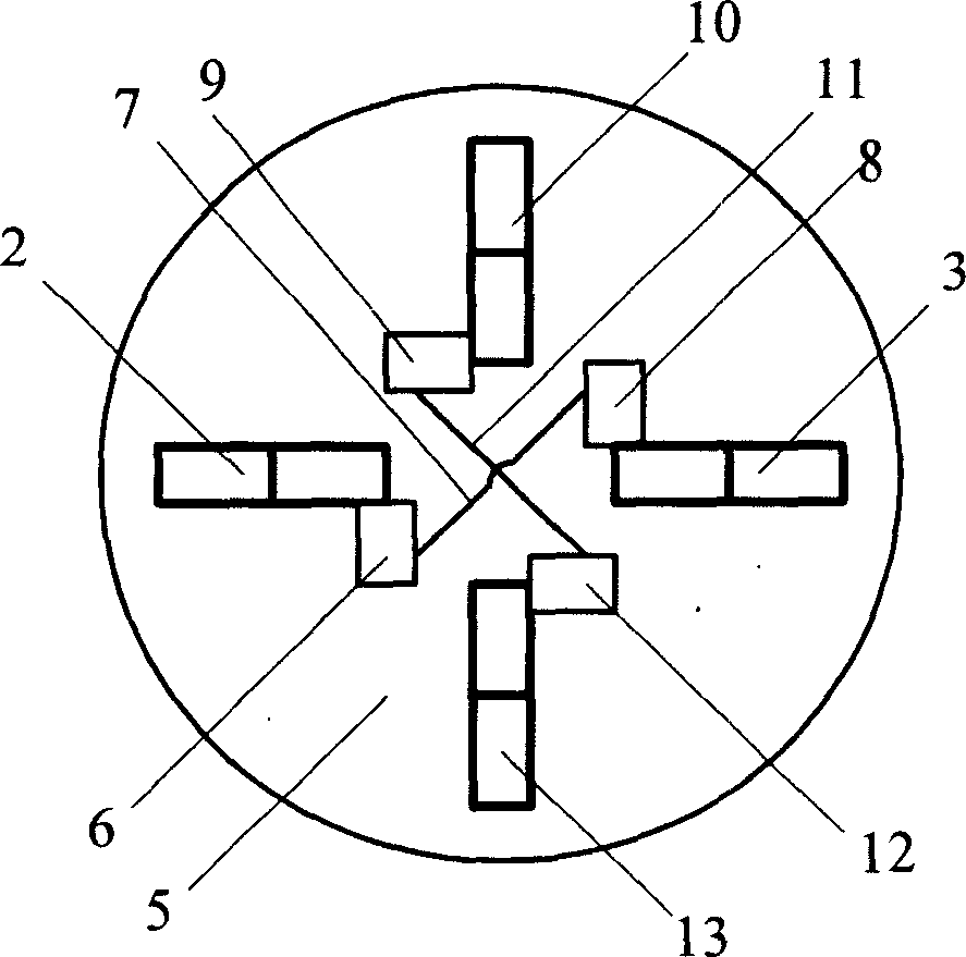
[0013] Such as figure 1 and figure 2 As shown, the present invention includes: four antenna units 2, 3, 10, 13, first and second feed ports 6, 9, first and second phase change units 8, 12, ground plate 5, connecting cable 1 , 4, 7, 11. The four antenna units 2, 3, 10, 13 are bow-shaped, and the two antenna units 2, 3 are paired with the first commutation unit 8 and the first feeding port 6 to form a symmetrical vibrator, so that the two vertical sections on the outside of the vibrator The currents are in the same direction, and the other two antenna units 10 and 13 are paired with the second feeding port 9 through the second commutation unit 12 to form a symmetrical oscillator, so that the currents on the two vertical segments outside the oscillator are in the same direction, and the two symmetrical oscillators are orthogonal , vertically placed and distributed on the grounding plate 5, arranged in the shape of a "ten" in the same plane, symmetrically distributed in the cen...


PUM


Abstract

The invention includes antenna units, feeder port, phase-change unit and landnig plate. The four antenna units are all above the landing plate and in arched shape, the two symmetric placed antenna unit through phase-change unit and feeder port to form a symmetric vibrator, the outer conduction of feeder port is connected with another antenna unit in the symmetric vibrator through phase-change unit, the length of connectnig cable between outer conduction of feeder port and phase-change unit is near to zero, the feeder port passes through the landing plate, the outer conduction of feeder port is connected with the landing plate.

Description

technical field [0001] The invention relates to an antenna used in the technical field of communication, in particular to a low-profile high-gain vertically polarized omnidirectional antenna. Background technique [0002] At present, wireless communication represented by mobile communication is developing rapidly. With the improvement of communication capacity, quality, content and other requirements and the development of integrated circuit technology, people pay more and more attention to multimedia digital communication methods. At the same time, mobile reception has become one of the main communication methods because it can greatly meet the needs of users. Therefore, higher and higher requirements are placed on the receiving antenna. For example, after the broadcast of digital TV, buses and various cars will be one of the main users. Most of the early vertically polarized antennas used dipoles or monopoles (such as whip antennas), but the height of this antenna was ha...

Claims


Application Information

Patent Timeline
IPC IPC(8): H01Q21/00H01Q21/06
Inventor 金荣洪周旭竹耿军平范瑜
Owner SHANGHAI JIAO TONG UNIV
Why Eureka
Try Eureka