Plasma etcher

A technology of plasma etching and plasma electrode, applied in the direction of plasma, discharge tube, electrical components, etc., can solve problems such as uneven gas distribution and uneven velocity

Inactive Publication Date: 2005-03-09
SAMSUNG ELECTRONICS CO LTD
View PDF0 Cites 2 Cited by
  • Summary
  • Abstract
  • Description
  • Claims
  • Application Information

AI Technical Summary

Problems solved by technology

Therefore, when there is a quality difference between the gases that make up the mixed gas, the velocity becomes uneven in the horizontal direction of diffusion, resulting in uneven distribution of the gas flowing into the box.

Method used


Image

  • Plasma etcher
  • Plasma etcher
  • Plasma etcher

Examples


Embodiment Construction

[0015] In order to enable those skilled in the art to practice the present invention, the preferred embodiments of the present invention will now be described in detail with reference to the accompanying drawings. However, the present invention may be embodied in different forms and is not limited to the embodiments described herein.

[0016] In the drawings, in order to clearly show the layers and regions, the thicknesses are enlarged to indicate, and the symbols of the same drawings are attached to similar parts throughout the specification. When referring to layers, films, regions, plates, etc. When "on", it means "directly" on top of other parts, and also includes the case where other parts are sandwiched in between, on the contrary, when a part is "directly" on top of other parts, it means that there is no other part in between. part.

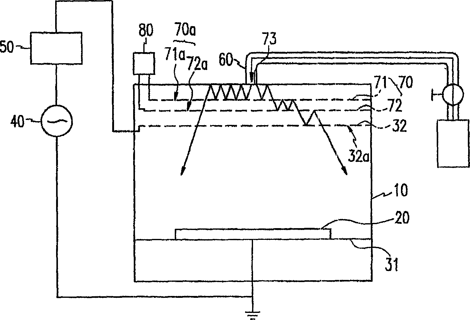
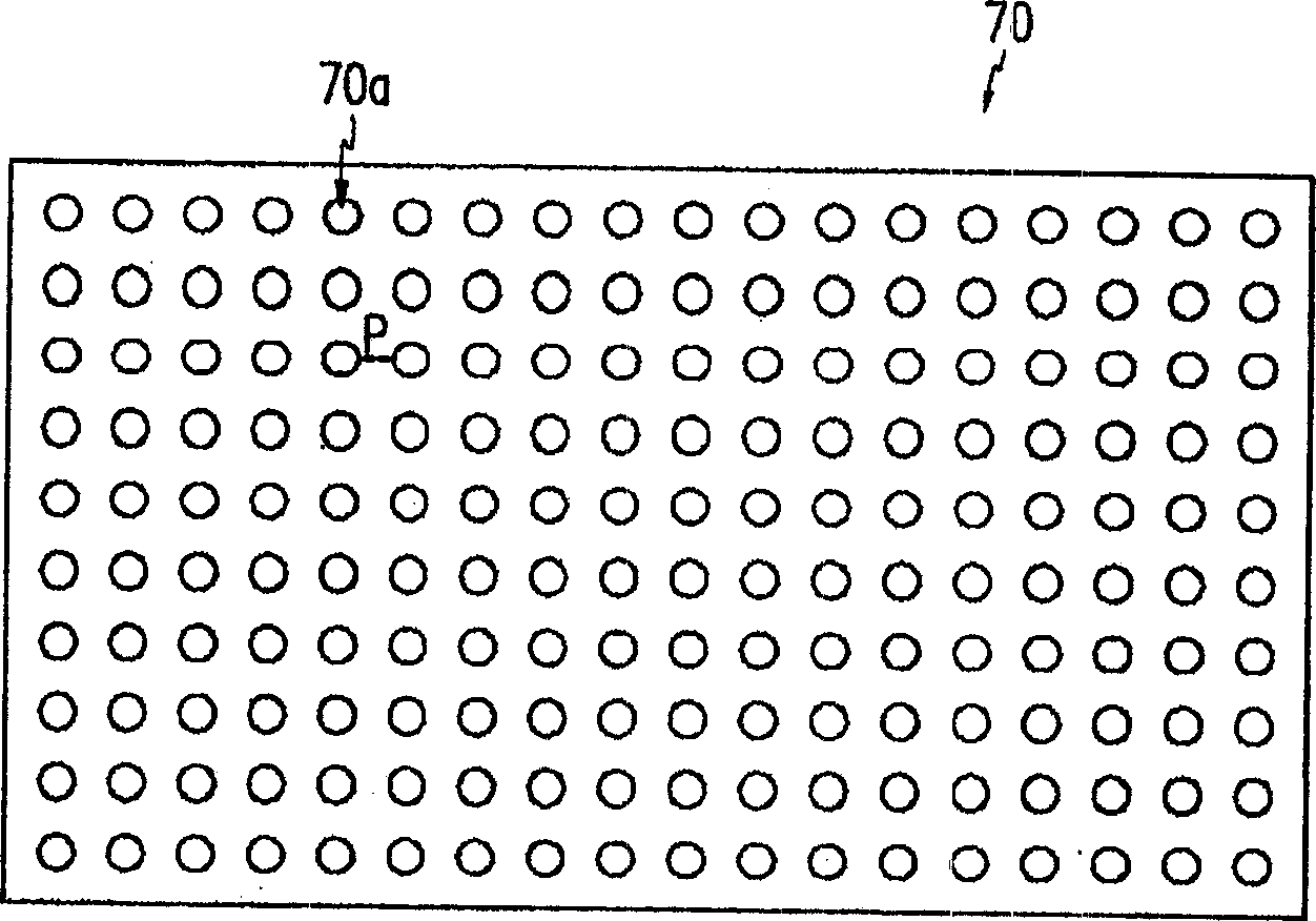
[0017] Hereinafter, a plasma etcher according to an embodiment of the present invention will be described in detail with reference to th...


PUM


Abstract

A plasma etcher is provided, which includes: a chamber; top and bottom plasma electrodes provided top and bottom positions of the chamber; a gas injection pipe connected to the chamber; a plurality of diffusion plates provided between the top plasma electrode and the gate injection pipe; and a power generator supplying a plasma voltage to the top and bottom electrodes, wherein the top plasma electrode has a plurality of primary injection holes and the diffusion plates have a plurality of secondary injection holes.

Description

technical field [0001] The present invention relates to a plasma etching machine, in particular to a plasma etching machine used in the manufacturing process of semiconductor elements or liquid crystal displays. Background technique [0002] In general, the plasma etching process is performed by injecting gas into the box through a gas injection pipe connected to the upper part of the plasma etching box. At this time, since a plurality of injection holes are formed in the upper electrode provided across the inside of the case, the gas supplied to the upper electrode by the gas injection pipe is sprayed onto the entire surface of the glass substrate inside the case through the injection holes. [0003] However, as the size of the glass substrate increases, the possibility of uneven injection of the gas injected into the interior of the case through the gas injection pipe also increases. [0004] In other words, when the gas flowing in from the gas injection pipe flows into t...

Claims


Application Information

Patent Timeline
Patent Type & Authority Applications(China)
IPC IPC(8): H05H1/46H01J37/32H01L21/3065
CPCH01J37/3244H01L21/3065
Inventor 崔熙焕姜聖哲金湘甲
Owner SAMSUNG ELECTRONICS CO LTD
Why Eureka
Try Eureka