Cooling apparatus

A cooling device and electronic device technology, applied in the direction of instruments, electrical digital data processing, electrical components, etc., can solve the problem of little contribution of the computer system, and achieve the effect of stable operation

Active Publication Date: 2005-04-27
WISTRON CORP
View PDF0 Cites 2 Cited by
  • Summary
  • Abstract
  • Description
  • Claims
  • Application Information

AI Technical Summary

Benefits of technology

This technology allows an improved cooling device with multiple components connected together without being restricted on one part only at once or requiring more space than what was previously possible due to its use of a metallic framework attached to the chilled plate's surface.

Problems solved by technology

This patented describes an improved way for computers with powerful processors to dissipate their excessive amount of thermal energy without losing performance. However, this improvement does little if anything about how much more efficient these systems are at once.

Method used


Image

  • Cooling apparatus
  • Cooling apparatus
  • Cooling apparatus

Examples


Embodiment Construction

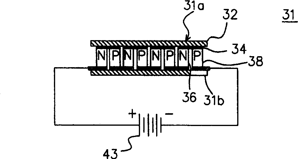
[0035] In order to enable those skilled in the art to better understand the spirit of the present invention, before describing various embodiments of the present invention, the principle of a thermoelectric cooler (TEC) is briefly introduced. Please refer to figure 2 , which shows a schematic structural diagram of a cooling chip that can be used in an embodiment of the present invention. The cooling chip 31 is composed of many semiconductor particles such as N-type semiconductor 36 and P-type semiconductor 38 arranged at intervals, and the material of these semiconductor particles is usually bismuth telluride. These semiconductor particles are connected by a metal conductor 34 to form a complete circuit, and the material of the conductor 34 is, for example, copper, aluminum or other metal conductors. Finally, two insulators 32 such as ceramic sheets sandwich the circuit formed by the entire semiconductor particle and the metal conductor 34 . The insulator 32 must be insulate...


PUM


Abstract

The present invention discloses one kind of cooling device set inside casing of electronic equipment to cool the whole system inside the casing. The electronic equipment has one tail part with at least one electronic part. The cooling device includes one refrigerating chip with cold surface adhered to the casing of the electronic equipment and hot surface; one metal frame configured inside the casing of the electronic equipment and coupled to the cold surface to conduct the cold airflow. The cold airflow convects with the heat the electronic elements inside the casing to carry the heat to the tail of the casing. The metal frame matching with the fan can dissipate the heat of all the electronic parts inside the electronic equipment.

Description


Claims


Application Information

Patent Timeline
Owner WISTRON CORP
Why Eureka
Try Eureka