Pneumatic injection valve

A jet valve, pneumatic technology, applied in the direction of coating, coating liquid on the surface, etc., can solve the problem that there is no good solution for the heat dissipation of the valve body, achieve a significant heat dissipation effect, simplify its own structure, and save work The effect of running costs

Active Publication Date: 2014-01-22
湖南汉科德科技有限公司
View PDF7 Cites 9 Cited by
  • Summary
  • Abstract
  • Description
  • Claims
  • Application Information

AI Technical Summary

Problems solved by technology

[0003] The injection valve of the prior art drives the piston to move through the air supply device, and the piston further drives the striker to hit the dispensing back and forth. The piston will generate a certain amount of heat during the reciprocating movement, and the injection valve of the prior art does not have much heat dissipation for the valve body. Good solutions have certain technical flaws

Method used


Image

  • Pneumatic injection valve
  • Pneumatic injection valve
  • Pneumatic injection valve

Examples


Embodiment Construction

[0032] The present invention will be described in detail below in conjunction with the accompanying drawings.

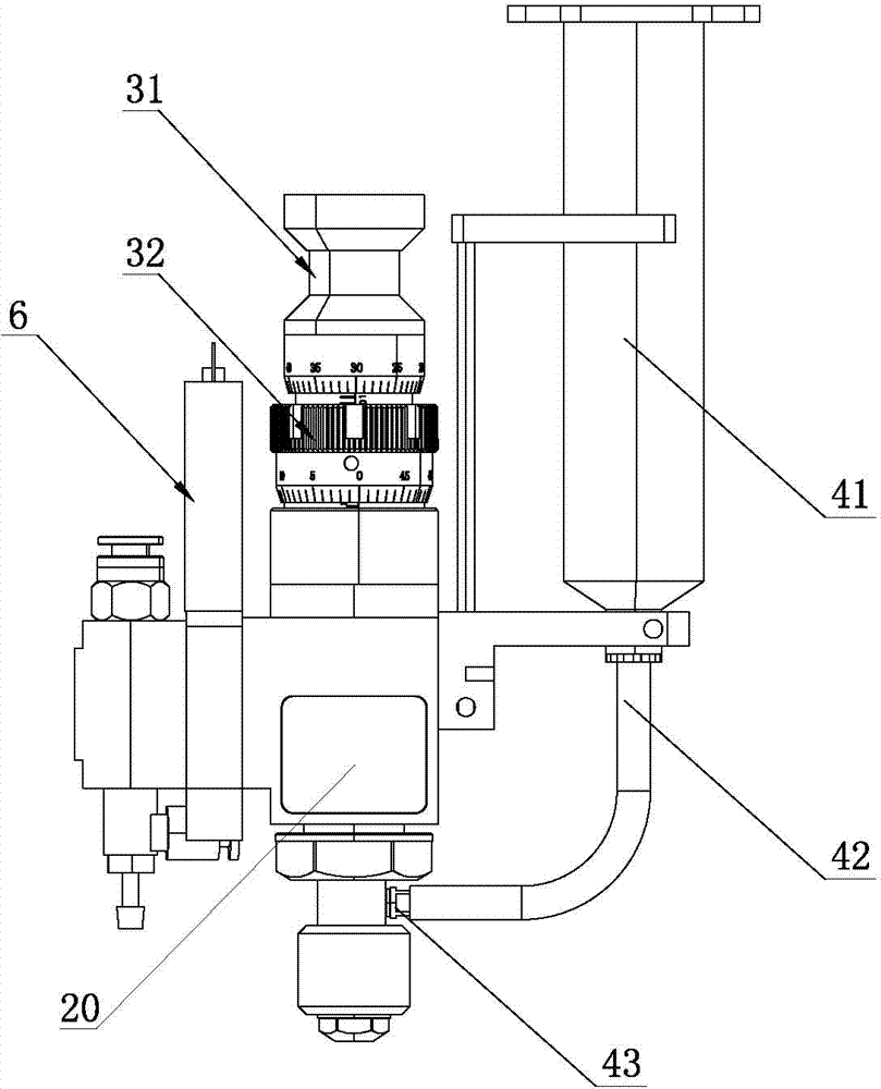
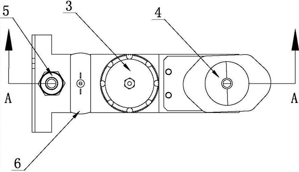
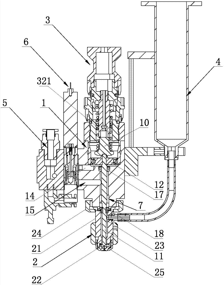
[0033] Such as Figure 1 to Figure 8 As shown, a pneumatic injection valve of the present invention includes a main valve body 1, the lower end of the main valve body 1 is provided with a nozzle assembly 2, and the upper end of the main valve body 1 is provided with a glue output adjusting device 3, The side of the main valve body 1 is connected with a feeding device 4 for feeding the nozzle assembly 2, and the other side of the main valve body 1 is connected with an air supply device 5, and the main valve body 1 and the nozzle assembly 2 There is a striker 11 inside, and the striker 11 is connected with the glue output adjustment device 3. A solenoid valve 6 for controlling the air intake and output of the main valve body 1 is arranged between the air supply device 5 and the main valve body 1. The upper end of the striker 11 is connected with a piston 12; the upper...


PUM


Abstract

The invention relates to the technical field of fluid dispensing equipment, in particular to a pneumatic injection valve. According to the pneumatic injection valve, when an air supplying device supplies air, an air inlet channel of a main valve body is opened and cooling channels of the main valve body are closed under the control of an electromagnetic valve, the air is controlled to enter the air inlet channel of the main valve body firstly, an air outlet of the air inlet channel is located below a piston, the air pushes the piston to move upwards, and the piston drives a striker to move upwards; when the striker moves to a certain height, the air supplying device stops supplying air, the cooling channels of the main valve body are opened under the control of the electromagnetic valve, an adjusting device is pre-tightened to enable the piston to be reset, coating materials are ejected at the closing moment of the striker, air inside a piston cavity is discharged by the piston through the cooling channels, and due to the fact that the cooling channels are distributed in different lateral sides of the interior of the main valve body, the heat of the main valve body can be taken away along with the discharging of the air, and then heat dissipation of the main valve body is achieved without the need of other media. The pneumatic injection valve is simple in structure and remarkable in heat dissipation effect.

Description

technical field [0001] The invention relates to the technical field of fluid dispensing equipment, in particular to a pneumatic jet valve. Background technique [0002] Fluid dispensing technology is a key technology in microelectronic packaging. It can be structured to form points, lines, surfaces (coating) and various graphics, and is widely used in chip fixing, package flipping and chip coating. This technology precisely distributes the fluid in a controlled manner, transferring the ideal size fluid (solder, conductive glue, epoxy and adhesive, etc.) To realize the mechanical or electrical connection between components, this technology requires the dispensing system to have good operating performance, high dispensing speed, good consistency and high precision of the dispensing glue dots. With the development of the packaging industry, the dispensing technology has gradually changed from contact dispensing to non-contact (jet) dispensing. [0003] The injection valve of ...

Claims


Application Information

Patent Timeline
Patent Type & Authority Applications(China)
IPC IPC(8): B05C5/02B05C11/10
Inventor 刘飞
Owner 湖南汉科德科技有限公司
Why Eureka
Try Eureka