
Centrifugal fan and its frame structure

A centrifugal fan and fan frame technology, which is applied to non-variable volume pumps, components of pumping devices for elastic fluids, machines/engines, etc., can solve the problem of uneven air output, reduce the cooling efficiency of centrifugal fans, reduction, etc.

Inactive Publication Date: 2005-05-11
DELTA ELECTRONICS INC
View PDF0 Cites 9 Cited by
  • Summary
  • Abstract
  • Description
  • Claims
  • Application Information

AI Technical Summary

Problems solved by technology

However, in a limited space, this method is not feasible, and it is easy to cause problems such as uneven air volume, noise, and reduced air volume.
Another known improvement technology is to increase the number and size of the blades, but due to the limited space, it will drive the rotation of the airflow, which will reduce the heat dissipation efficiency of the centrifugal fan itself

Method used


Image

  • Centrifugal fan and its frame structure
  • Centrifugal fan and its frame structure
  • Centrifugal fan and its frame structure

Examples


Embodiment Construction

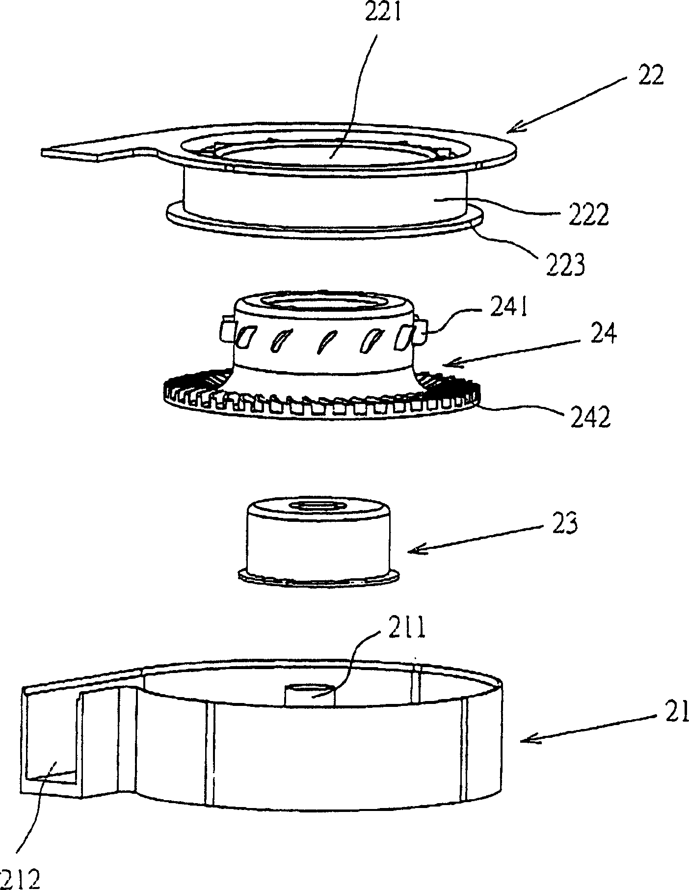
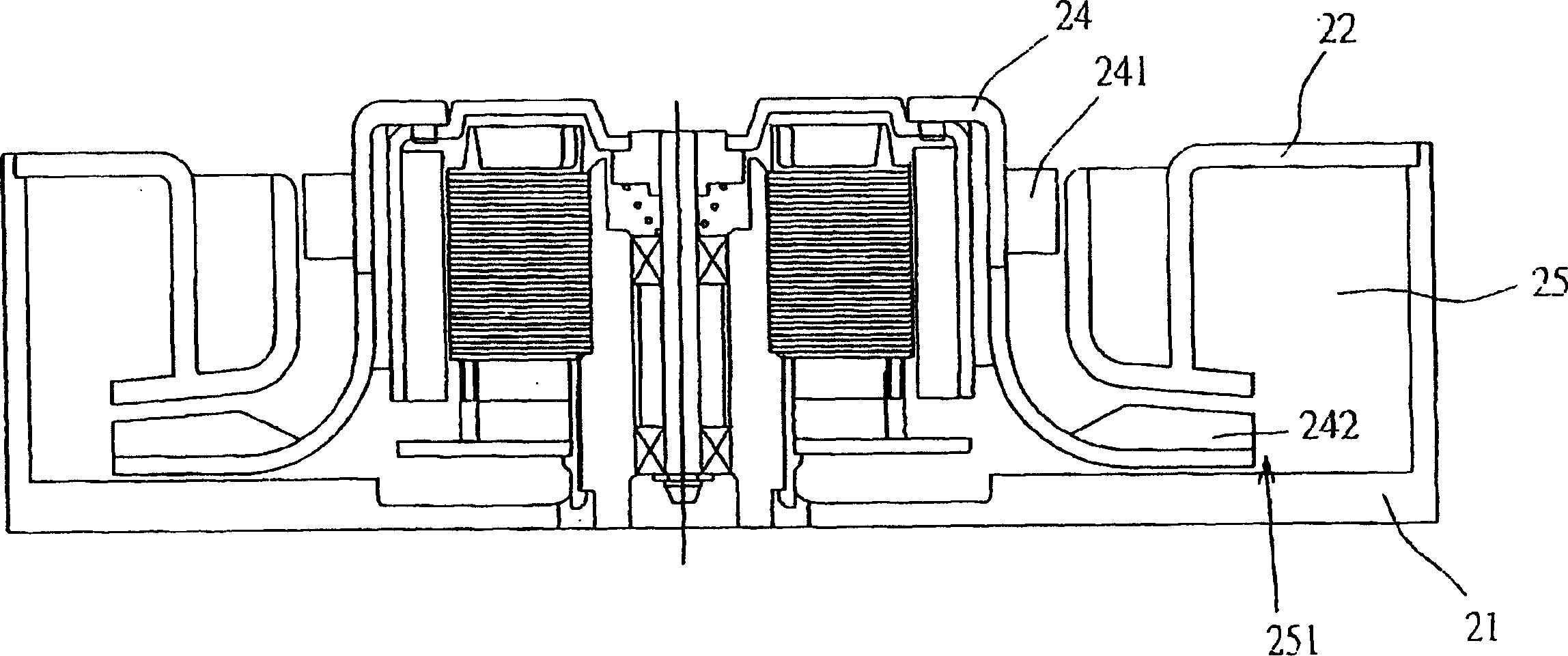
[0026] see Figure 2A and 2B , which shows the first preferred embodiment of the centrifugal fan of the present invention. The centrifugal fan is a one-way blower, which mainly includes a first frame 21 , a second frame 22 , a driving device 23 and a moving blade 24 . The first frame 21 has a sleeve seat 211, so that the driving device 23 can be placed on it, and the second frame 22 has an air inlet 221 and a wall 222 extending downward from the inner edge of the air inlet. After the second frame 22 is combined with the first frame 21, the wall surface 222 forms an air collecting channel 25 in the space formed by the combination of the second frame 22 and the first frame 21 and accommodates the moving blade. The space of the part 24 also forms an air outlet 212 at the same time. The bottom end of the wall has a radially outwardly extending flange 223 for forming an inlet 251 of the flow collecting channel. The moving blade part has a first blade group 241 and a second blad...


PUM


Abstract

A centrifugal fan is composed of a fan frame with at least one air inlet and one air outlet, and at least one rotary blade unit arranged in said fan frame and with at least one group of blades. The internal boundary of said air inlet has an extended wall to form an air gathering channel for increasing wind pressure and heat dissipating efficiency.

Description

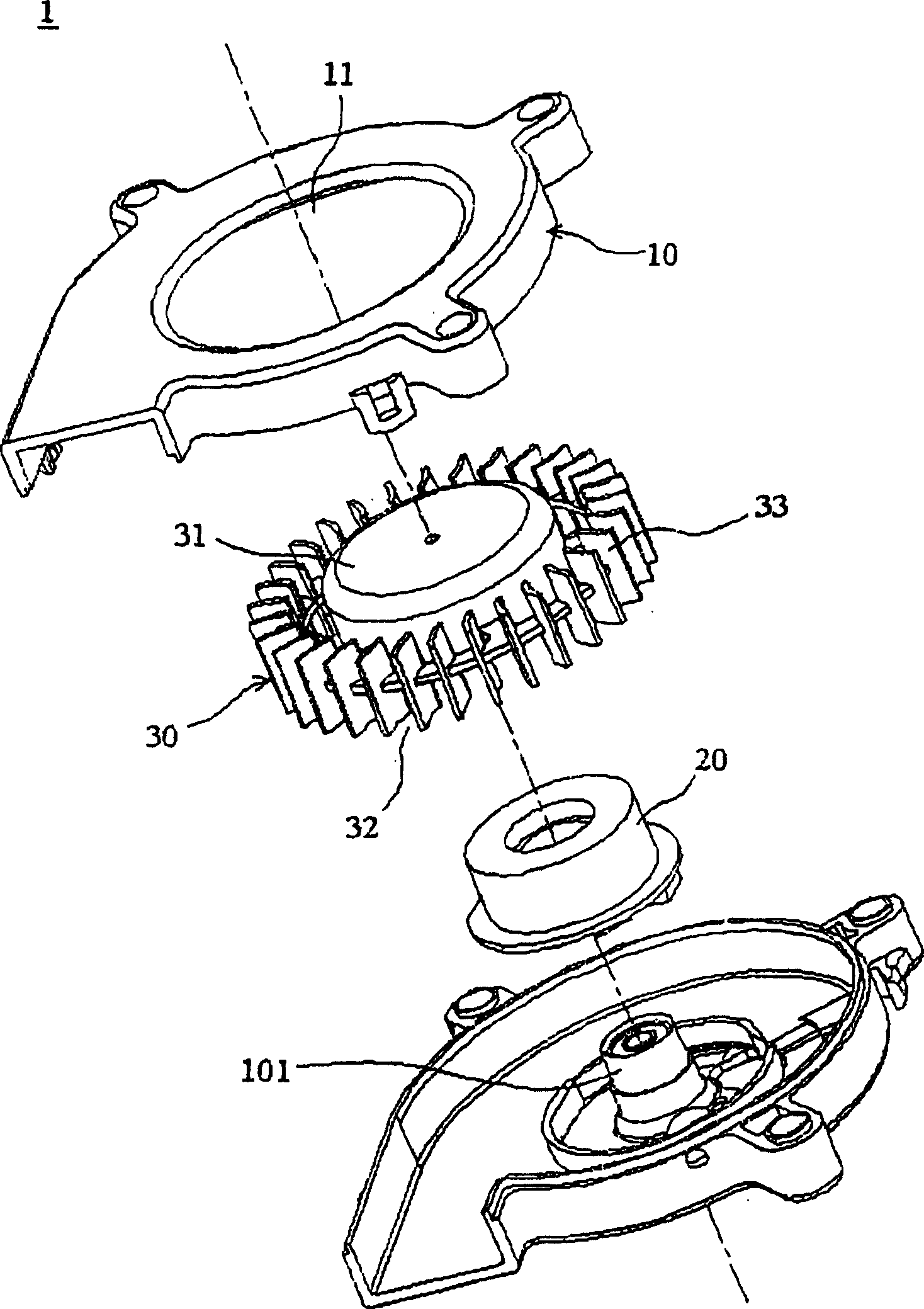
(1) Technical field [0001] The invention relates to a centrifugal fan, in particular to a centrifugal fan capable of increasing wind pressure and its fan frame structure. (2) Background technology [0002] Commonly known blowers, such as figure 1 As shown, it includes an outer frame 10, a motor 20 and a blade structure 30, wherein the outer frame 10 has an air inlet 11 and an exhaust port (not shown), and the motor 20 is sleeved on the base of the outer frame 10 101 for rotating the blade structure 30 . The blade structure 30 further includes a hub 31 , a bottom plate 32 and a plurality of vanes 33 formed thereon. In this traditional blower design, since the blades are in direct contact with the flow channel, and the upper and lower air gaps of the blades are large, it is difficult to control the direction of the airflow, and it is easy to cause air backflow, resulting in low heat dissipation efficiency. [0003] Therefore, as the efficiency of the electronic components i...

Claims


Application Information

Patent Timeline
Patent Type & Authority Applications(China)
IPC IPC(8): F04D29/54
Inventor 张楯成黄文喜
Owner DELTA ELECTRONICS INC
Learn More