
Configuration for monitoring the state of components in a packet-switched communications network

A technology of packet switching network, communication device, applied in the field of devices for monitoring components in a communication network

Inactive Publication Date: 2005-05-11
SIEMENS AG
View PDF0 Cites 1 Cited by
  • Summary
  • Abstract
  • Description
  • Claims
  • Application Information

AI Technical Summary

Problems solved by technology

[0005] It has proven to be a disadvantage in different installations that the service of monitoring the status of subscribers within a communication network is limited to the subscribers on a single communication device or to the users of a small number of communication devices comprised in a network, respectively

Method used


Image

  • Configuration for monitoring the state of components in a packet-switched communications network
  • Configuration for monitoring the state of components in a packet-switched communications network

Examples


Embodiment Construction

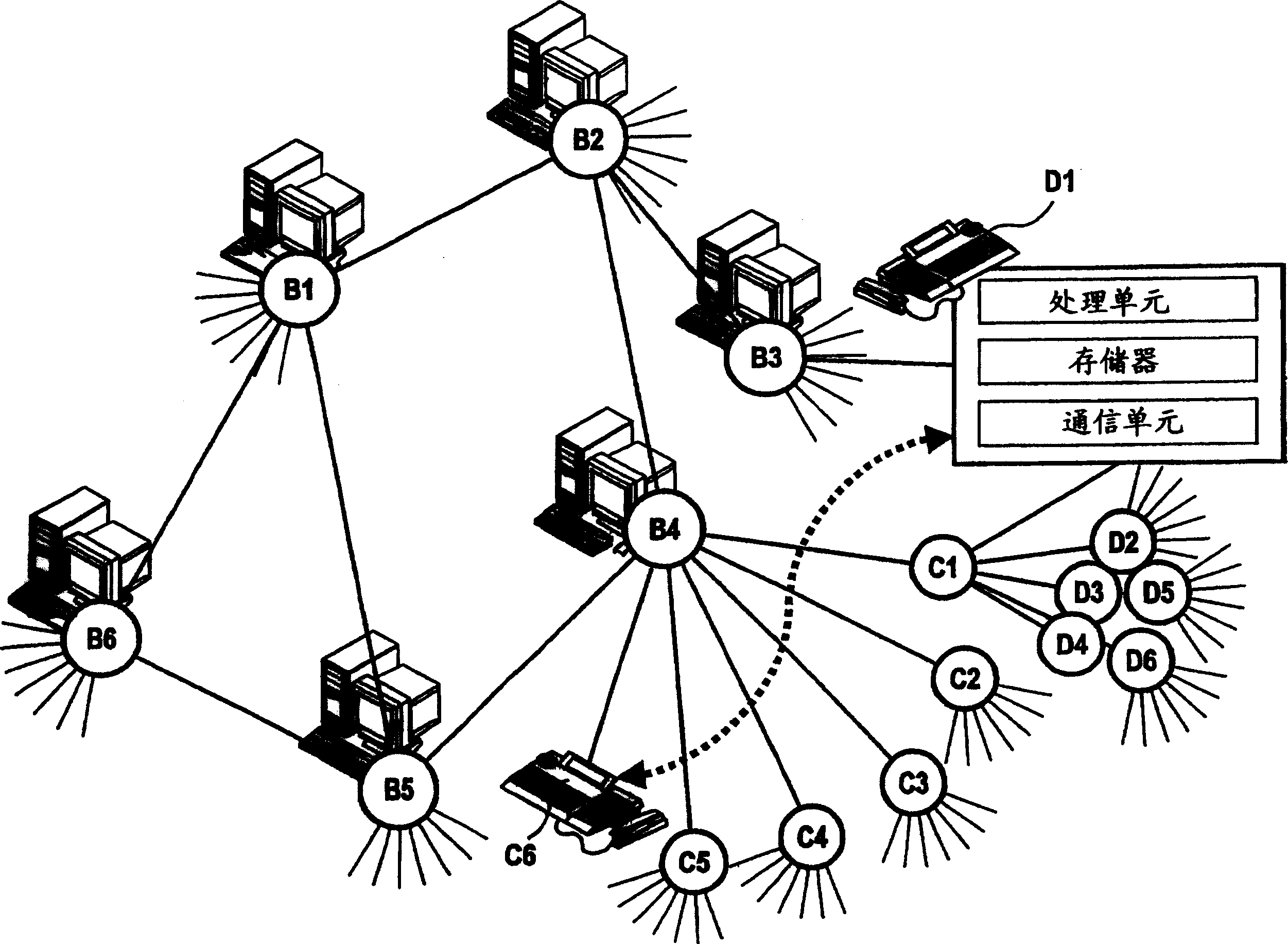
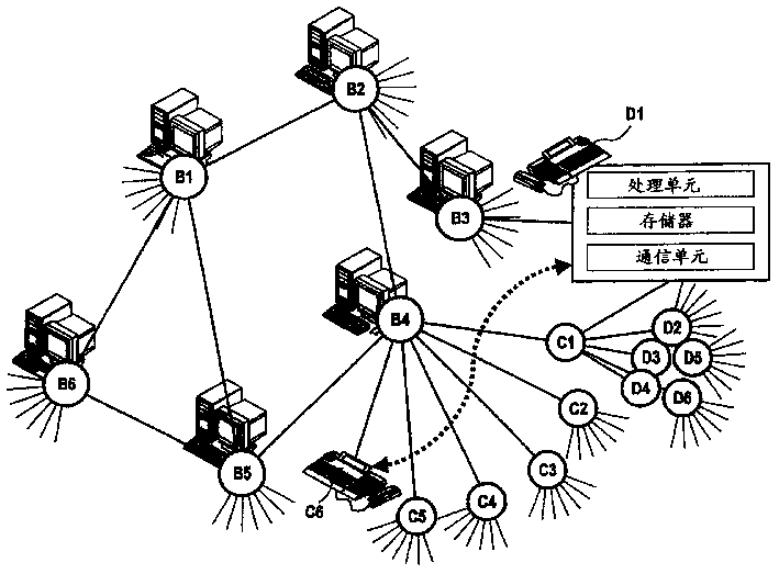
[0018] All components B1-B6, C1-C6, D1-D6 of the communication network are interconnected via a packet switched network (IP network). The network is here a hybrid of ring and star connections. In principle, other mesh connections are also possible, as long as it is ensured that the components B1 - B6 , C1 - C6 , D1 - D6 can exchange data with each other either directly or indirectly, that is to say via intermediate connections of other components. In the figures, the line segments between components B1-B6, C1-C6, D1-D6 represent data connections. The components B1-B6 configured as servers can provide switching functions in the communication network. This function is also called the gatekeeper function. In the gatekeeper, a direct dial number, which is also known in circuit-switched telephony, is assigned to a network address (IP address). That is to say, a gatekeeper, for example component B1, is used to establish a communication link between two components C6, D1. However...


PUM


Abstract

In the communication network, one component (B1-B6, C1-C6, D1-D6) can each be monitored by at least one other component (B1-B6, C1-C6, D1-D6). For this purpose, a monitoring command is assigned by the monitoring component (C6), the command including the address of this component (C6). Each monitorable and monitoring component (D1, C6) has communication means for direct data exchange. The monitoring component (C6) directly transmits the monitoring command to the component to be monitored (D1), which has storage means for monitoring addresses contained in the command and monitoring means for state monitoring. The state to be monitored is communicated directly to the monitoring means ( C6 ) at least when the state changes using a communication device.

Description

technical field [0001] The invention relates to a device for monitoring components in a communication network. Background technique [0002] It is known that in modern communication networks it is necessary to monitor, for example, the switching status of other users of the same communication device. Therefore, it is displayed for each user on the seat of the communication device by means of an assigned light control panel or by means of a PC application whether he is free or occupied or in a call state. [0003] In addition, terminals on the communication device are often equipped with direct call keys, with which other users of the same communication device can be called by pressing a button. Most of these direct call buttons are equipped with LEDs or other display elements, whereby the switching status of the relevant subscriber is displayed by lighting up or flashing the LEDs. [0004] If several PC applications are running on a communication device, the information ab...

Claims


Application Information

Patent Timeline
Patent Type & Authority Applications(China)
IPC IPC(8): G06F15/16H04L12/26H04L12/56H04M11/00H04Q3/00
CPCH04L43/0817H04L43/10H04Q3/0087H04Q2213/13034H04Q2213/13389
Inventor R·纽豪斯R·厄克尔
Owner SIEMENS AG
Learn More