
A compressor control method and device

A control method and compressor technology, applied in the field of compressors

Active Publication Date: 2020-06-02
BAIC GRP ORV CO LTD
View PDF11 Cites 0 Cited by
  • Summary
  • Abstract
  • Description
  • Claims
  • Application Information

AI Technical Summary

Problems solved by technology

[0003] Embodiments of the present invention provide a compressor control method and a vehicle to solve the problem that the existing compressor is at a specific speed during operation

Method used


Image

  • A compressor control method and device
  • A compressor control method and device
  • A compressor control method and device

Examples


Embodiment Construction

[0048] The technical solutions in the embodiments of the present invention will be clearly and completely described below in conjunction with the accompanying drawings in the embodiments of the present invention. Obviously, the described embodiments are part of the embodiments of the present invention, not all of them. Based on the embodiments of the present invention, all other embodiments obtained by those of ordinary skill in the art without creative work shall fall within the protection scope of the present invention.

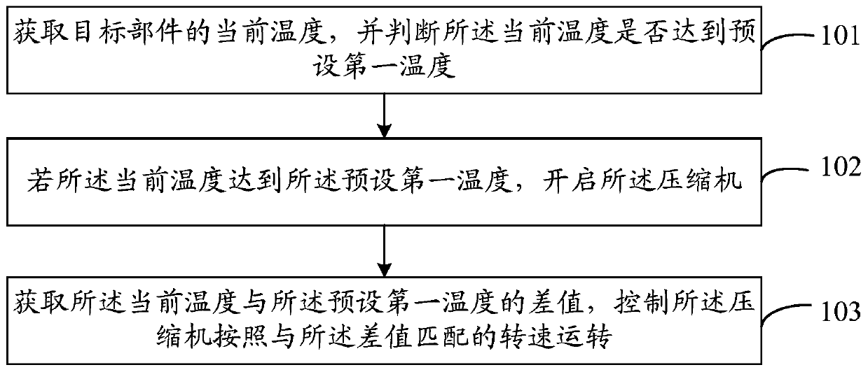
[0049] See figure 1 , figure 1 Is a flowchart of a compressor control method provided by an embodiment of the present invention, such as figure 1 As shown, including the following steps:

[0050] Step 101: Obtain the current temperature of the target component, and determine whether the current temperature reaches a preset first temperature.

[0051] It should be noted that the target component is connected to the compressor. Specifically, the compressor is an el...


PUM


Abstract

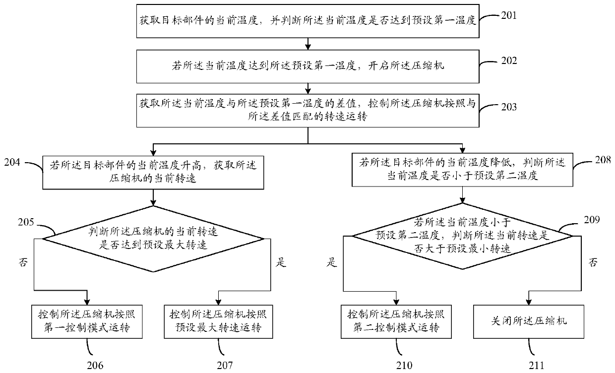
The invention provides a compressor control method and device as well as a vehicle. The compressor control method comprises the following steps of: obtaining a current temperature of a target part, and judging whether the current temperature reaches a preset first temperature or not, wherein the target part is connected with a compressor; starting the compressor if the current temperature reachesthe preset first temperature; and obtaining a difference value between the current temperature and the preset first temperature, and controlling the compressor to operate according to a rotation speedmatched with the difference value. The technical scheme provided by the invention solves the problem that an existing compressor has a specific rotation speed in an operation process.

Description

Technical field [0001] The present invention relates to the technical field of compressors, in particular to a compressor control method and device. Background technique [0002] Compressors are widely used in systems such as air conditioners and refrigerators because they provide power for refrigeration cycles. With the rapid development of science and technology, the compressor is constantly undergoing technological innovation. The typical transformation is to replace the traditional compressor driven by a belt with an electric compressor driven by high-voltage electricity. However, most of the existing control schemes of electric compressors are ON / OFF mode. When the system conditions are reached, the compressor is turned on, and the compressor operates at a specific speed until the compressor is turned off. In this way, the compressor is at a specific speed during operation, so that the speed of the compressor does not match the system load. Summary of the invention [0003]...

Claims


Application Information

Patent Timeline
Patent Type & Authority Patents(China)
IPC IPC(8): F04B49/06
CPCF04B49/065F04B2201/1201F04B2207/03
Inventor 周舟高志强王东芳
Owner BAIC GRP ORV CO LTD
Learn More