
Speed reducer

A technology of reducer and input shaft, which is applied in the direction of portable lifting device, transmission device parts, gear transmission device, etc., can solve the problems of low transmission efficiency, single function, low precision, etc., and achieve obvious work efficiency, simple operation and excellent structure reasonable effect

Inactive Publication Date: 2016-11-16
ANHUI HANSHAN COUNTY ANHUI PROVINCE IN THE SLOWDOWN MACHINERY
View PDF5 Cites 0 Cited by
  • Summary
  • Abstract
  • Description
  • Claims
  • Application Information

AI Technical Summary

Problems solved by technology

At present, most of the reducers on the market have complicated assembly, single function, large structure, low transmission efficiency and low precision, so they need to be improved urgently.

Method used


Image

  • Speed reducer

Examples


Embodiment Construction

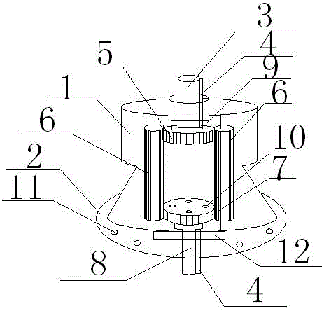
[0013] Such as figure 1 As shown, a reducer, the reducer includes a reducer housing 1 and an output end cover 2; the top of the reducer housing 1 is provided with an input shaft 3; the bottom of the input shaft 3 is connected to the main gear 5 through a slot 4 ; The two sides of the main gear 5 are provided with a driven gear 6; the bottom of the driven gear 6 is meshed with the output gear 7 through the gear teeth; the output shaft 8 is set in the middle of the output end cover 2; the output shaft 8 It is connected to the output gear 7 through the card slot 4.

[0014] The intersecting part of the main gear 5 and the input shaft 3 is provided with a radiator 9, and the radiator 9 is made of an aluminum alloy material. When the input shaft 3 works, the power is relatively large and a large amount of heat will be generated. In order to avoid the generated heat Affecting the work of the reducer, the heat must be dissipated, and the aluminum alloy material not only has a good h...


PUM


Abstract

The invention discloses a speed reducer. The speed reducer comprises a speed reducer casing, an output end cover, an input shaft and an output shaft; both the input shaft and the output shaft are provided with locking slots; the top of the speed reducer casing is provided with an input shaft ; The bottom of the input shaft is connected to the main gear through the card slot; the driven gear is arranged on both sides of the main gear; the bottom of the driven gear is engaged with the output gear through the teeth; shaft; the output shaft is connected to the output gear through a card slot. The speed reducer of the present invention has the advantages of reasonable structure, excellent function of matching rotating speed and transmitting torque, simple operation, long service life, obvious working efficiency and the like.

Description

technical field [0001] The invention relates to a speed reducer. Background technique [0002] The reducer is generally used for transmission equipment with low speed and high torque. The power of the electric motor, internal combustion engine or other high-speed operation is achieved by the gear with a small number of teeth on the input shaft of the reducer meshing with the large gear on the output shaft to achieve the purpose of deceleration. It is a relatively precise machine, the purpose of using it is to reduce the speed and increase the torque. It has a wide variety, different models, and different types have different uses. At present, most reducers on the market have complex assembly, single function, large structure, low transmission efficiency and low precision, so they need to be improved urgently. Contents of the invention [0003] In order to overcome the defects of the prior art mentioned above, the object of the present invention is to provide a speed redu...

Claims


Application Information

Patent Timeline
Patent Type & Authority Applications(China)
IPC IPC(8): F16H1/22F16H55/06F16H55/17F16H57/04
CPCF16H1/22F16H55/06F16H55/17F16H57/0412
Inventor 吕才友
Owner ANHUI HANSHAN COUNTY ANHUI PROVINCE IN THE SLOWDOWN MACHINERY
Learn More