Supercharge Your Innovation With Domain-Expert AI Agents!

Injection molding machine

A technology of injection molding machine and injection device, which is applied in the field of injection molding machines, can solve the problems that there is no rib plate and it is difficult to prevent the fixed pressure plate from toppling over, and achieve the effect of preventing toppling

Inactive Publication Date: 2005-05-18
FANUC LTD
View PDF2 Cites 5 Cited by
  • Summary
  • Abstract
  • Description
  • Claims
  • Application Information

AI Technical Summary

Problems solved by technology

[0005] Even if the fixed platen is prevented from toppling over by providing a rib (or extension) at the bottom of the fixed platen and fixing the rib to the base frame, the part that applies the nozzle contact force to the fixed platen It is located at the center of the locating hole in the center of the fixed platen, so it is above the rib, so it is difficult to prevent the fixed platen from tipping due to the contact force of the nozzle.
[0006] Also, in small injection molding machines, since the entire injection molding machine is made compact, there are cases where there is no space for ribs extending to the injection mechanism on the bottom of the fixed platen (the part on the side of the base frame)

Method used


Image

  • Injection molding machine
  • Injection molding machine
  • Injection molding machine

Examples


Embodiment Construction

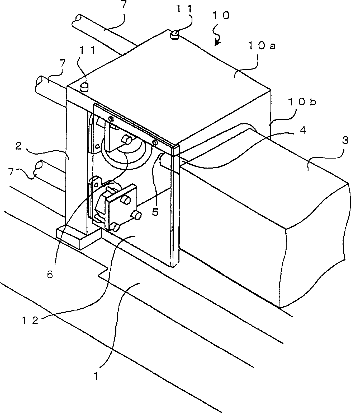
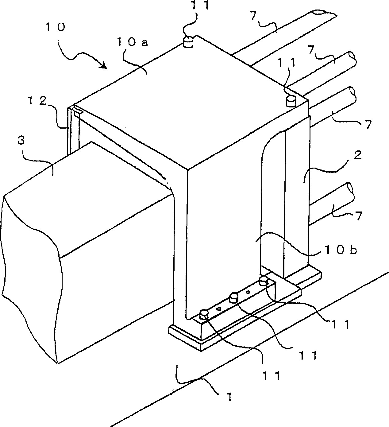
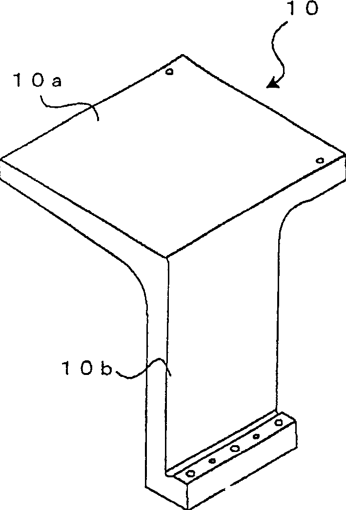
[0025] First, use Figure 1-Figure 3 , to describe the first implementation side of the injection molding machine of the present invention

[0026] The fixed platen 2 is fixed on the base frame 1 of the injection molding machine. The fixed platen 2 is connected to the rear platen (not shown) through a plurality of tie rods 7 . A fixed-side metal mold (not shown) is fixed to the fixed platen 2 . In addition, a movable side metal mold is attached to a movable platen (not shown) movable along the tie rod 7 . The mold is closed and closed by the movement of the movable platen.

[0027] In addition, on the base frame 1, the injection device 3 is installed so as to be able to advance and retreat in the direction of the fixed platen 2, and is installed so as to be rotatable around a vertical axis through a rotary joint. The nozzle 5 is arranged on the front end of the heating cylinder 4 installed on the injection device 3, and when the injection device 3 advances, the nozzle 5 pa...


PUM


Abstract

The connecting part is composed of the upper plate part and the side plate part, and one end of the upper plate part is fixed on the fixed platen of the injection molding machine, and the lower end of the side plate part is fixed on the base frame on which the fixed platen is fixed. This connecting member can prevent the fixed platen from falling when the nozzle contact force generated by the injection device is applied.

Description

technical field [0001] The present invention relates to an injection molding machine, and more particularly, to an injection molding machine intended to prevent tipping of a fixed platen caused by a nozzle contact force generated by an injection device. Background technique [0002] In the injection molding machine, a fixed metal mold is installed on a fixed platen fixed to the base frame of the injection molding machine, and a movable metal mold is installed on a movable platen that can move back and forth relative to the fixed platen, so that The moving platen moves forward to close the metal mold, and the mold is closed. In addition, the injection device is moved forward, and the injection nozzle is pressed into the sprue bushing of the fixed metal mold from the non-movable platen side of the fixed platen, and the contact force of the nozzle is applied to move the injection screw forward, thereby Molten resin is injected into the closed metal mold. [0003] The bottom o...

Claims


Application Information

Patent Timeline
Patent Type & Authority Applications(China)
IPC IPC(8): B29C45/17B29C45/84
CPCB29C45/1744B29C45/1775B29C45/1777B29C2045/1797
Inventor 吉冈光志桥本展明
Owner FANUC LTD
Features
  • R&D
  • Intellectual Property
  • Life Sciences
  • Materials
  • Tech Scout
  • Unparalleled Data Quality
  • Higher Quality Content
  • 60% Fewer Hallucinations
Learn More