
Hydraulic cylinder controlled hydraulic transformer
A technology of hydraulic transformers and hydraulic cylinders, applied in the field of hydraulic transformers, can solve problems such as no good solutions and restricted applications, and achieve the effects of rapid and flexible control response, reliable control, and reduced volume
- Summary
- Abstract
- Description
- Claims
- Application Information
AI Technical Summary
Problems solved by technology
Method used
Image

Examples
Embodiment Construction
[0024] The present invention will be further described below in conjunction with the drawings and embodiments.
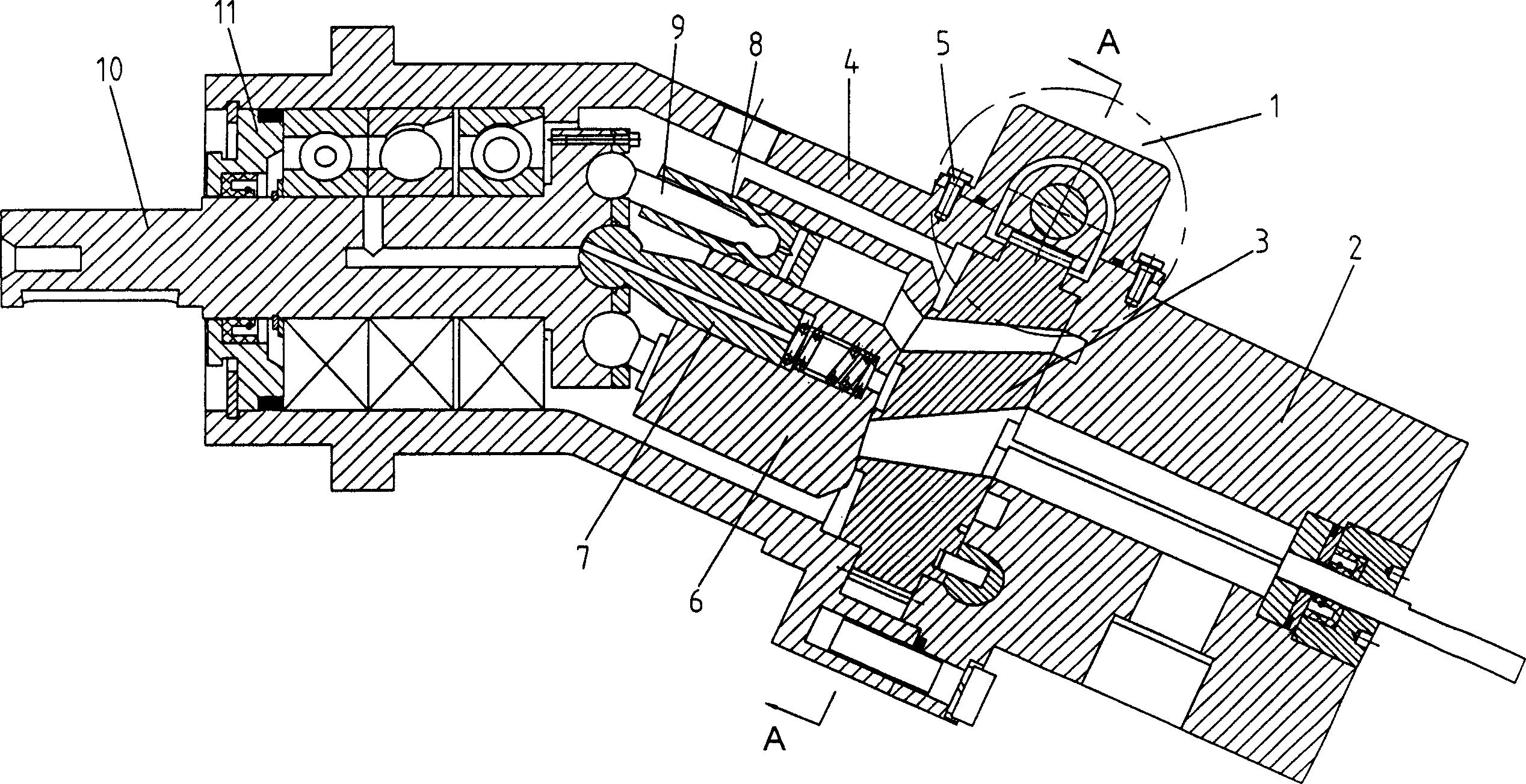
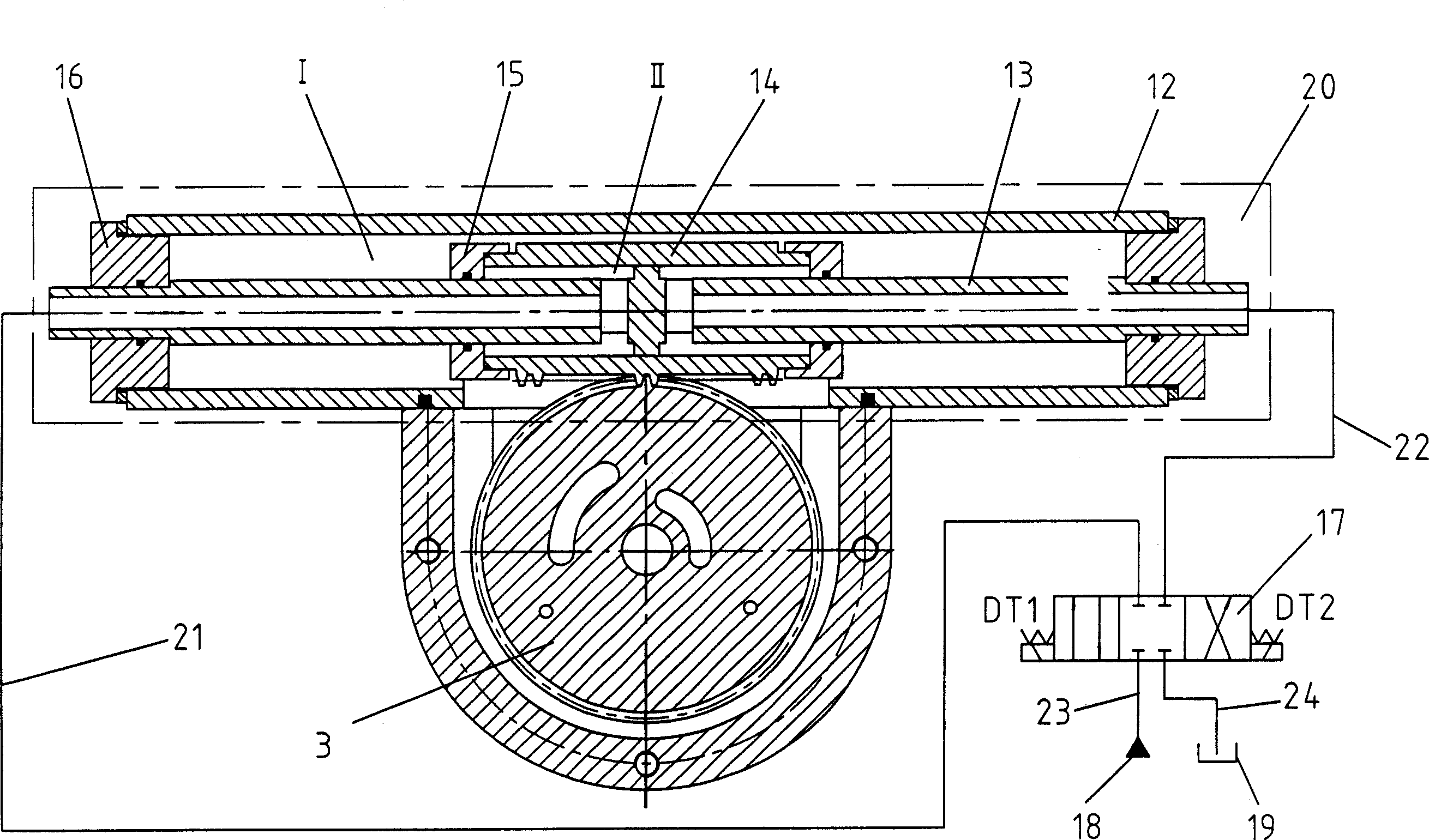
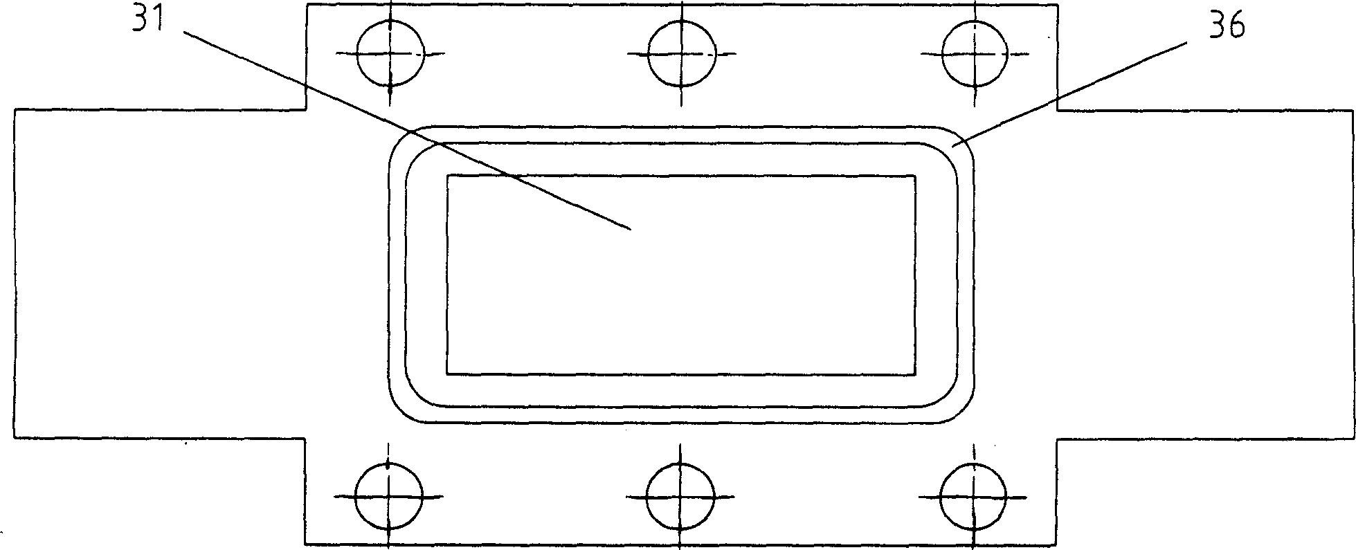
[0025] Such as figure 1 As shown, the hydraulic transformer housing is mainly composed of a housing 4, a back end cover 2 and a front end cover 11. The housing 4 is fastened to the back end cover 2 and the front end cover 11; the main shaft 10 and the cylinder are installed inside the housing 4 The body 6, the valve plate 3, the central shaft 7, the connecting rod 9, the plunger 8, the main shaft 10 is installed on the bearing in the housing 4, one end of the central shaft 7 is installed in the ball socket of the main shaft 10, and the other end is installed in the cylinder The plunger 8 is connected to one end of the connecting rod 9 by rolling, and the other end of the connecting rod 9 is connected to the ball socket of the main shaft 10. The plunger 8 is installed in the plunger cavity of the cylinder 6, The valve plate 3 is installed between the cylinder block 6 an...
PUM
 Abstract
Description
Claims
Application Information