Rapid response electric heat exchanger

A technology for heat exchangers and rapid heating, applied in the field of fluid heat exchangers and fluid fluid heat exchangers, which can solve the problems of not being easy to manufacture, and the Rezabek system does not have a compact structure, etc.

Inactive Publication Date: 2005-06-01
WATLOW ELECTRIC MFG
View PDF2 Cites 6 Cited by
  • Summary
  • Abstract
  • Description
  • Claims
  • Application Information

AI Technical Summary

Problems solved by technology

Also, due to the space required between the pipes, the Rezabek system is not compact nor easy to manufacture

Method used


Image

  • Rapid response electric heat exchanger
  • Rapid response electric heat exchanger
  • Rapid response electric heat exchanger

Examples


Embodiment Construction

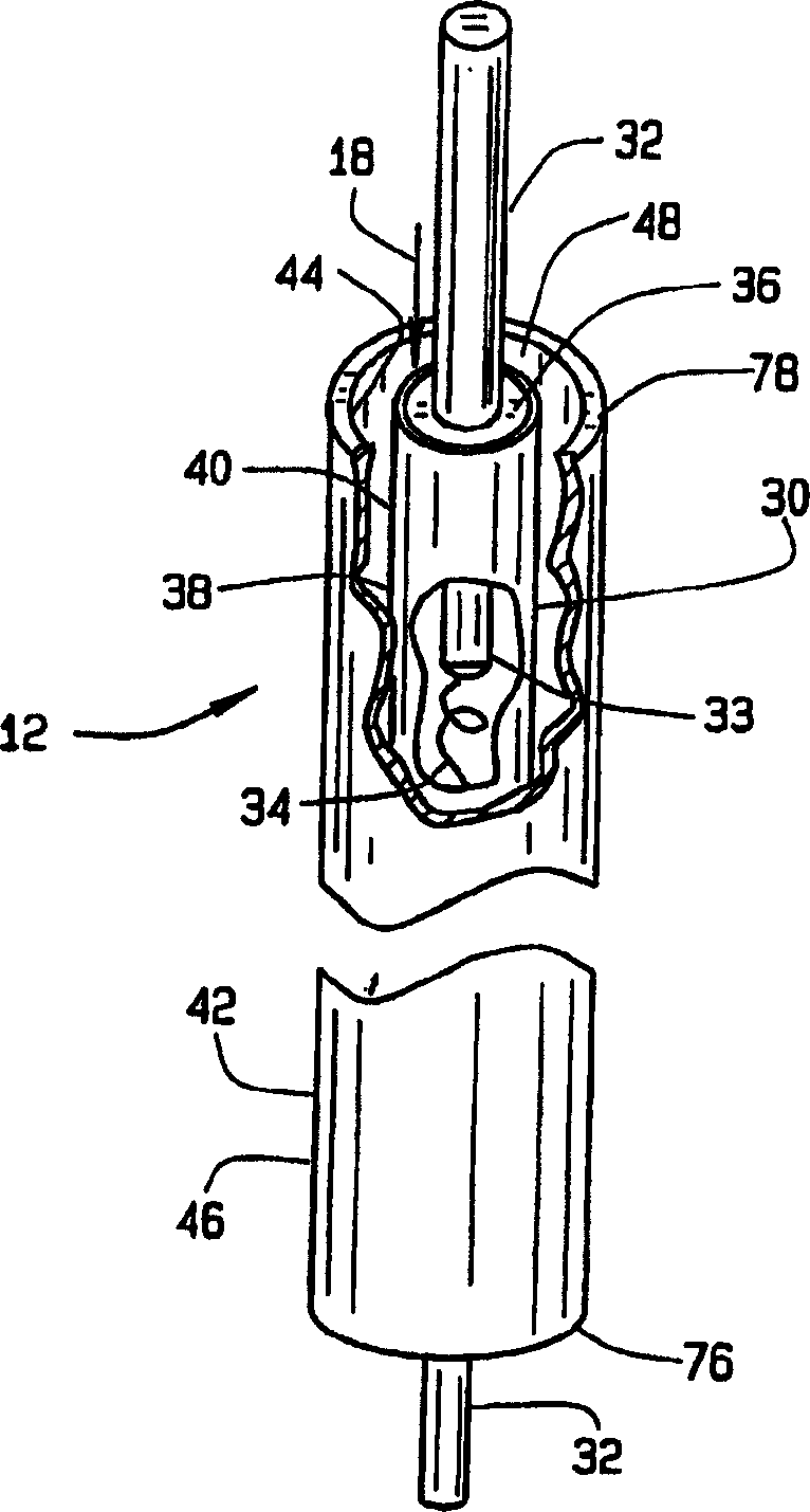
[0036] Referring to the drawings, a preferred embodiment of the fluid heating system of the present invention is shown in FIG. 4 and generally designated 10 . The fluid heating system 10 includes a housing 13 containing a body 17 defining an elongated upper portion 25 and a lower portion 26 having a fluid heat exchanger 12 disposed therein providing means for heating a fluid 18 to a predetermined temperature. heating equipment. Fluid 18 enters upper section 25 from return side 22 of fluid heating system 10 and is heated while flowing along upper section 25 and lower section 26 . The heated fluid 18 then exits the lower portion 26 and flows into the inlet side 24 and through the remainder of the fluid heating system 10 . Once circulated, the fluid 18 flows through the return side 22 so that the above process is repeated. The temperature level of the fluid 18 is maintained by a temperature control system 20 .

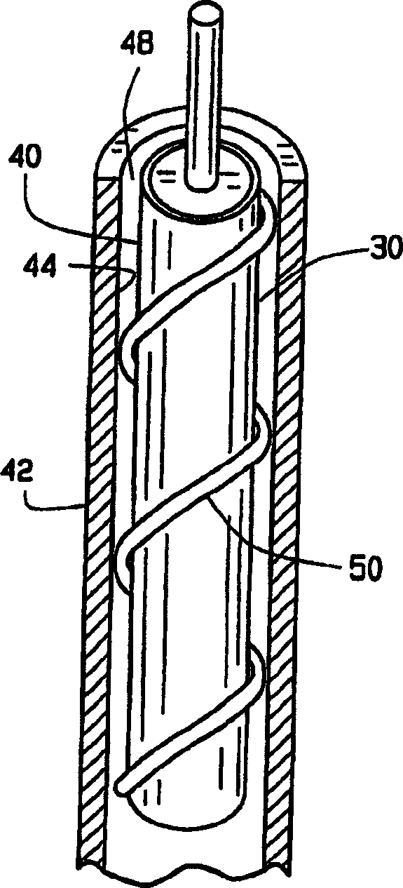
[0037] 1 and 4, the fluid heat exchanger 12 includes an elongated...


PUM


Abstract

A fluid heat exchanger (12) for use in a fluid heating system (10) is disclosed comprising a rapidly heatable inner tube (30) surrounded by a hollow outer tube (42) for heating fluid flowing through the fluid (18) between the inner tube (30) and the outer tube (42), and circulates the fluid within the fluid heating system (10). When the inner tube (30) is rapidly heated, the circulating fluid (18) is rapidly heated to the predetermined temperature used in the fluid heating system (10).

Description

technical field [0001] The invention relates to a heat exchanger, especially a fluid heat exchanger. More specifically, the present invention relates to a fluid heat exchanger capable of rapidly heating a fluid flowing between two tubes of the heat exchanger. Background technique [0002] Typically, fluid heating systems consist of a metallic resistive coil, called a heating element, wound around the outside of a hollow tube. Fluid flows through the tube and is heated by the heating element; however, this arrangement has several disadvantages. Prior art heating systems are not efficient at heating fluids, especially at low fluid flow rates. In addition, such heating systems do not readily form compact shapes and require additional time to heat the fluid to the predetermined temperature used in the fluid heating system. [0003] An improvement on the prior art is found in US Patent No. 5,590,240 to Rezabek, which discloses a fluid heating system comprising an insulated she...

Claims


Application Information

Patent Timeline
Patent Type & Authority Applications(China)
IPC IPC(8): F24H1/10F24H9/20
CPCF24H1/102F24H9/2028
Inventor 丹尼斯·P·朗克里斯托弗·W·科佐特
Owner WATLOW ELECTRIC MFG
Why Eureka
Try Eureka