Connect method of heat-shrinkable sleeve

A heat-shrinkable sleeve and connection method technology, which is applied to tubular items, household appliances, other household appliances, etc., can solve the problems of high air leakage rate, fire hazard in lighter sintering method, and cut fingers, etc., and achieve sealing performance. Good results

Active Publication Date: 2005-06-08
深圳市沃尔热缩有限公司
View PDF0 Cites 11 Cited by
  • Summary
  • Abstract
  • Description
  • Claims
  • Application Information

AI Technical Summary

Problems solved by technology

The current connection methods include lighter sintering method, hot tongs pressing method and knotting method. However, these three methods have disadvantages: lighter sintering method has fire hazards, and conflicts with relevant national safety regulations. The clamping method is the

Method used


Image

  • Connect method of heat-shrinkable sleeve
  • Connect method of heat-shrinkable sleeve
  • Connect method of heat-shrinkable sleeve

Examples


Embodiment Construction

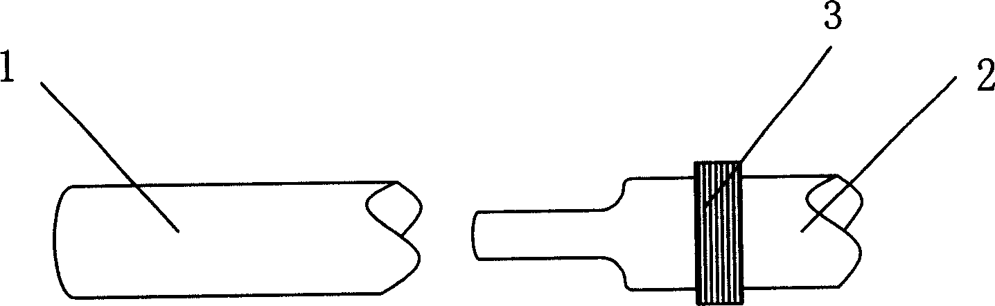
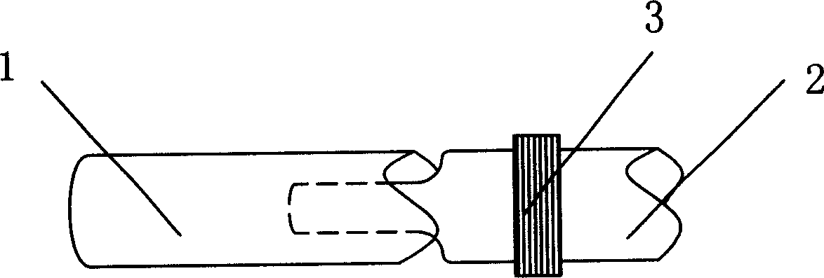
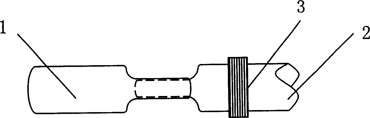
[0016] see Figure 1 to Figure 4 A method for connecting heat-shrinkable sleeves of the present invention is to connect and seal at least two sections of sleeves to form an overall airtight heat-shrinkable sleeve, that is, the heat-shrinkable sleeve has at least two sections of sleeves , and the outermost ends of the two outermost sections of the heat-shrinkable sleeve are sealed ends, and the method includes a connecting step and a sealing step. This connection step is to connect two adjacent sections of casing, and define the two sections of casing as the first casing 1 and the second casing 2 respectively. One and the two ends of the second casing 1, 2, aim the butt end of the first casing 1 at the heat source and heat for a few seconds to pre-shrink. At this time, the diameter of the butt end of the first casing 1 becomes smaller, and then the end Dock and insert into the butt end of the second casing 2, and then align the butt joints of the first and second sleeve 1, 2 wi...


PUM


Abstract

A method for connecting two thermal shrinkage sleeve tubes with each other includes such steps as heating one end of a sleeve tube for shrinking it, inserting it in the end of another sleeve tube, heating the connection position for shrinking it, heating the sealing end of external sleeve tube, and pressing for sealing.

Description

【Technical field】 [0001] The invention relates to the field of heat-shrinkable sleeves, in particular to a connection method for heat-shrinkable sleeves. 【Background technique】 [0002] Heat-shrinkable materials refer to basic materials that are irradiated with high-energy rays and transform linear molecular chains into three-dimensional structures with "shape memory" properties. After heating and expansion, the material will automatically shrink back to its original state after heating, which is heat shrinkage. [0003] Heat-shrinkable sleeves, especially ultra-thin thin tubes, are generally filled with compressed air when the finished product is rolled up and packaged to ensure that it will not be wrinkled and deformed. When more than two sleeves are contained in a minimum package (ie a reel), they must be joined. The current connection methods include lighter sintering method, hot tongs pressing method and knotting method. However, these three methods have disadvantages...

Claims


Application Information

Patent Timeline
IPC IPC(8): B29C61/02B29C65/66
Inventor 周和平彭雄心肖扬华肖炳敦
Owner 深圳市沃尔热缩有限公司
Why Eureka
Try Eureka