Battery receiving device

A storage device and battery technology, applied to battery circuit devices, circuit devices, battery pack components, etc., can solve problems such as difficulty in maintaining contact state

Inactive Publication Date: 2005-06-08
CANON KK
View PDF0 Cites 6 Cited by
  • Summary
  • Abstract
  • Description
  • Claims
  • Application Information

AI Technical Summary

Problems solved by technology

[0013] In addition, since the positive contact portion 41 of the positive contact terminal 4 is the part that the user contacts every time the battery 1 is exchanged, the shape of the top portion of the positive contact portion 41 is not “concave-convex sha

Method used


Image

  • Battery receiving device
  • Battery receiving device
  • Battery receiving device

Examples


Embodiment Construction

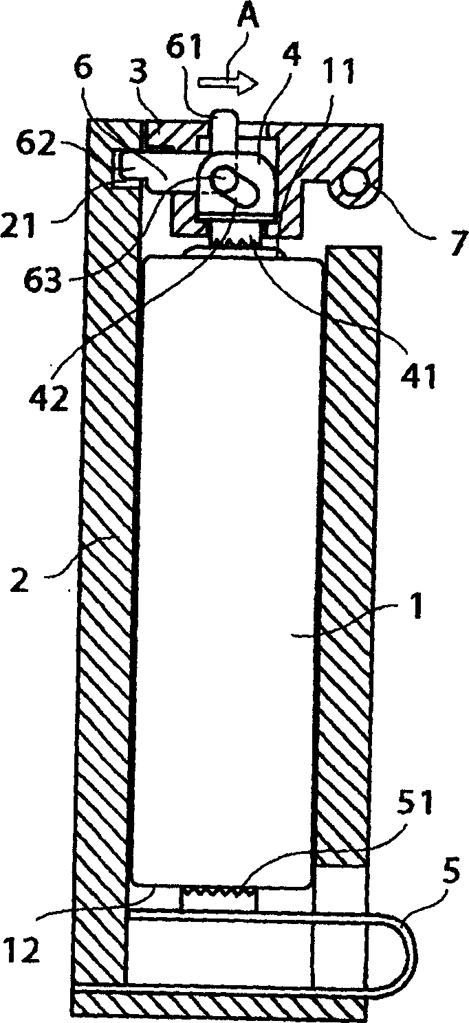
[0025] For example, the No. 3 battery 1 constituting the power supply of the main body of the device is cylindrical, has a positive terminal part 11 at the top part, and a negative terminal part 12 at the bottom, and supplies power to the main body of the device ( figure 1 ).

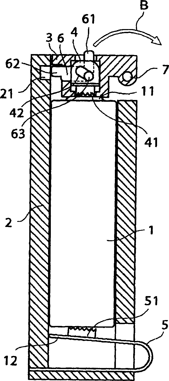
[0026] figure 1 It is a cross-sectional view showing a schematic configuration of a battery storage chamber provided with a battery cover according to an embodiment of the present invention, and shows a state in which the battery cover is closed and locked.

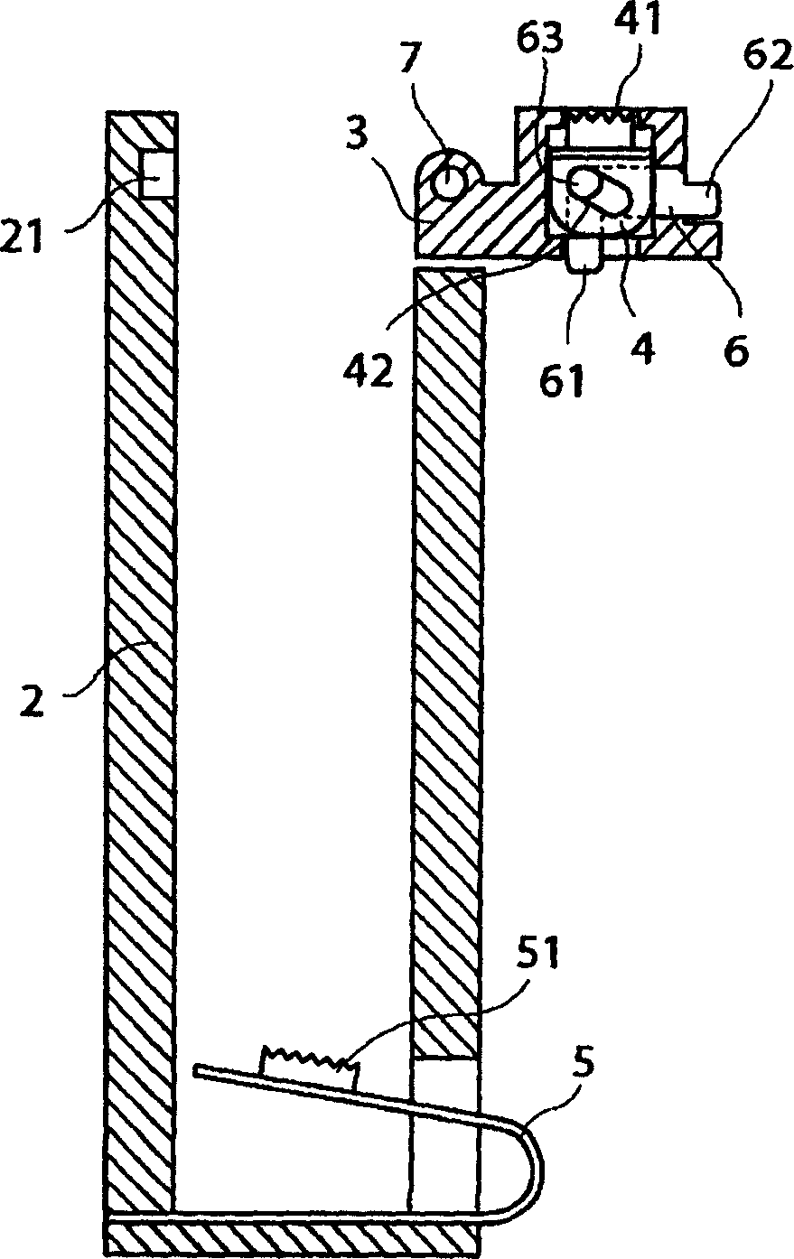
[0027] figure 1 Among them, the device main body (not shown) has a battery storage chamber 2 for accommodating the battery 1, and the battery storage chamber 2 has a battery cover 3 at its top end that opens and closes the opening of the battery storage chamber 2 through a hinge pin 7.

[0028] The battery cover 3 has a cavity in its interior, in which cavity the positive contact terminal 4 is accommodated. The lower end of the positive conta...


PUM


Abstract

The present invention provides a battery storage device, the battery storage device is installed in the main body of the device to accommodate the battery in order to keep the contact state of the contact part of the contact terminal and the battery terminal part in good condition while maintaining the safety of the user when the battery is replaced. , which is characterized in that it has a battery cover configured to open and close the opening of the above-mentioned battery storage device, and can be locked when closed; The contact terminal is in contact with the contact portion of the battery terminal when the battery cover is closed. The contact terminal is configured such that when the battery cover is closed and the battery cover is locked, the contact portion protrudes toward the inside of the battery cover. When the lock is released , the above-mentioned contact portion is pulled into the above-mentioned battery cover.

Description

technical field [0001] The present invention relates to a battery storage device for storing batteries, and an imaging device using the battery storage device. Background technique [0002] For example, the No. 3 battery 1 constituting the power supply of the main body of the device is cylindrical, has a positive terminal part 11 at the top part, and a negative terminal part 12 at the bottom, and supplies power to the main body of the device ( Image 6 ). [0003] Image 6 It is a cross-sectional view of a schematic configuration of a conventional battery storage room, showing a state in which the battery cover is closed. [0004] Image 6 Among them, the device main body (not shown) has a battery storage chamber 2 for accommodating the battery 1, and the battery storage chamber 2 has a battery cover 3 at its top end that opens and closes the opening of the battery storage chamber 2 by a hinge pin. [0005] The battery cover 3 has a cavity inside it, in which the positive c...

Claims


Application Information

Patent Timeline
IPC IPC(8): H01M50/147H02J7/00H04N5/225H05K5/00
CPCY02E60/10H01M50/147H01M50/213
Inventor 户叶兼义
Owner CANON KK
Why Eureka
Try Eureka