Microscopy laboratory system

一种显微镜、实验室的技术,应用在显微镜实验室系统领域,能够解决教师无法评注学生图像、效率差等问题

Inactive Publication Date: 2005-07-20
LEICA MICROSYSTEMS CMS GMBH
View PDF2 Cites 8 Cited by
  • Summary
  • Abstract
  • Description
  • Claims
  • Application Information

AI Technical Summary

Problems solved by technology

Obviously, this system is less efficient since the teacher has to spend time checking the students' microscopes instead of instructing the students
Another shortcoming is that teachers cannot comment on images from students' microscopes, which could better provide constructive criticism or positive reinforcement

Method used


Image

  • Microscopy laboratory system
  • Microscopy laboratory system
  • Microscopy laboratory system

Examples


Embodiment Construction

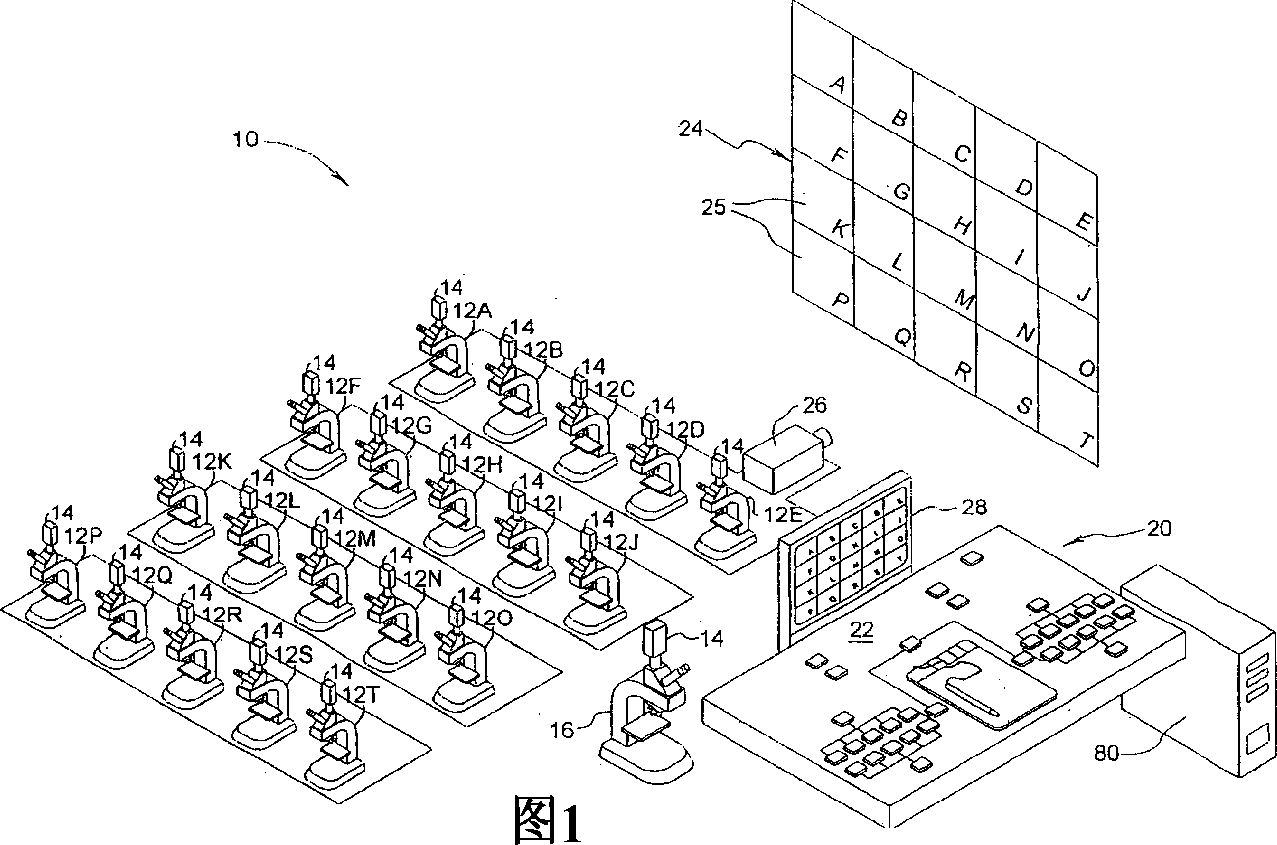
[0015] Referring first to Figure 1 of the accompanying drawings and figure 2 , the microscope laboratory system constituted according to the first embodiment of the present invention is generally identified by reference numeral 10 . The microscope laboratory system 10 includes a plurality of student microscopes 12A-12T each equipped with a video camera 14 for generating an image signal representative of at least a portion of the student observation image of the corresponding field of view of the student microscope; 14 is a teacher's microscope 16, the camera is used to generate an image signal representing at least a part of the teacher's observation image of the teacher's microscope 16 field of view. Camera 14 is preferably a retro-fitted or video camera integrated with the microscope via a C-mount, trinocular attachment, or an integrated video module inserted between the microscope base frame and the binocular display tube . As a non-limiting example, the Leica ICC A and L...


PUM


Abstract

A microscopy laboratory system for efficient instruction is disclosed. The system comprises a plurality of student microscopes each equipped with a camera for generating an image signal representing a student view image of at least a portion of the field of view of the student microscope, multiplexed control means connected by video cables or wireless technology to the cameras to provide a composite instruction image signal based on student view images from one or more selected microscopes, and a projection unit or other public display for presenting the instruction image to the students in the laboratory. An instructor microscope can also be coupled into the system, and a display image marker is preferably linked to the multiplexed control means for inserting instructor annotations into the displayed instruction image.

Description

technical field [0001] The present invention relates generally to teaching settings where participants view specimens through their own microscopes, and more particularly to microscope laboratory systems where teachers and students can view a full teaching image that selectively includes one, some or all of the specimens in the laboratory. Image of the microscope field of view. Background technique [0002] Microscopy laboratories at universities and teaching hospitals etc. are known to include television monitors or projection units that receive image signals from the teacher's microscope mounted on the teacher's microscope via a C-mount interface, trinocular viewing volume, video module, or the like. camera. This way, each student in the lab can view the image as a model to help him or her position the same specimen on his or her own microscope and adjust specimen position, objective power, focus, illumination , filters and other parameters of the microscope to match the...

Claims


Application Information

Patent Timeline
Patent Type & Authority Applications(China)
IPC IPC(8): G02B21/00G02B21/36G09B5/08G09B5/12G09B5/14G09B19/00G09B23/22G09B23/24G09G5/397H04N5/38H04N5/74H04N7/18H04N9/12
CPCG09B19/00G09B5/14H04N5/38G09B23/22G09B5/08G09B23/24G02B21/367G09B5/12H04N5/74H04N9/12G09B23/28G09B5/10
Inventor 文森特·瓦卡雷利
Owner LEICA MICROSYSTEMS CMS GMBH
Why Eureka
Try Eureka