Pre-forming device in hollow structure high-pressure forming process

A technology of internal high pressure forming and hollow structure, which is applied in the direction of forming tools, metal processing equipment, manufacturing tools, etc., and can solve the problems of large section deformation, flash defects, and waste products in local areas

Active Publication Date: 2005-07-27
哈尔滨工达海卓智能成形科技有限公司
View PDF0 Cites 15 Cited by
  • Summary
  • Abstract
  • Description
  • Claims
  • Application Information

AI Technical Summary

Problems solved by technology

However, for a hollow member with a complex cross-section, if you want to form a rectangular or other shape cross-section from the circular cross-section of the pipe in one step, when the pipe bent to the shape of the axis of the final part is put into the mold, some part of the pipe during the mold clamping process These parts are often extruded out of the mold cavity to form flash defects, resulting in waste
At the same time, there may be excessive deformation or uneven deformation of the section in the local area.

Method used


Image

  • Pre-forming device in hollow structure high-pressure forming process
  • Pre-forming device in hollow structure high-pressure forming process
  • Pre-forming device in hollow structure high-pressure forming process

Examples


specific Embodiment approach 1

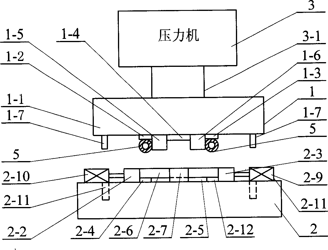
[0005] Specific implementation mode one: the following combination Figure 1 to Figure 6 This embodiment will be specifically described. It consists of an upper die 1, a lower die 2 and a press 3. The upper top surface of the upper die 1 is fixedly connected to the lower end of the pressure head 3-1 of the press 3. The lower die 2 is arranged below the upper die 1. The upper die 1 Consists of the upper mold bottom plate 1-1, the upper module of the left arm 1-2, the upper module of the right arm 1-3, the upper module of the forearm 1-4, the upper inner module of the left arm 1-5, and the upper inner module of the right arm 1- 6 and guide columns 1-7, the elongated left-arm upper-side inner module 1-5 and right-arm upper-side inner module 1-6 are respectively distributed on the left half of the lower surface of the upper mold bottom plate 1-1 in the front and rear direction And on the right half, the module 1-2 on the left arm is fixed on the lower surface of the upper mold bo...

specific Embodiment approach 2

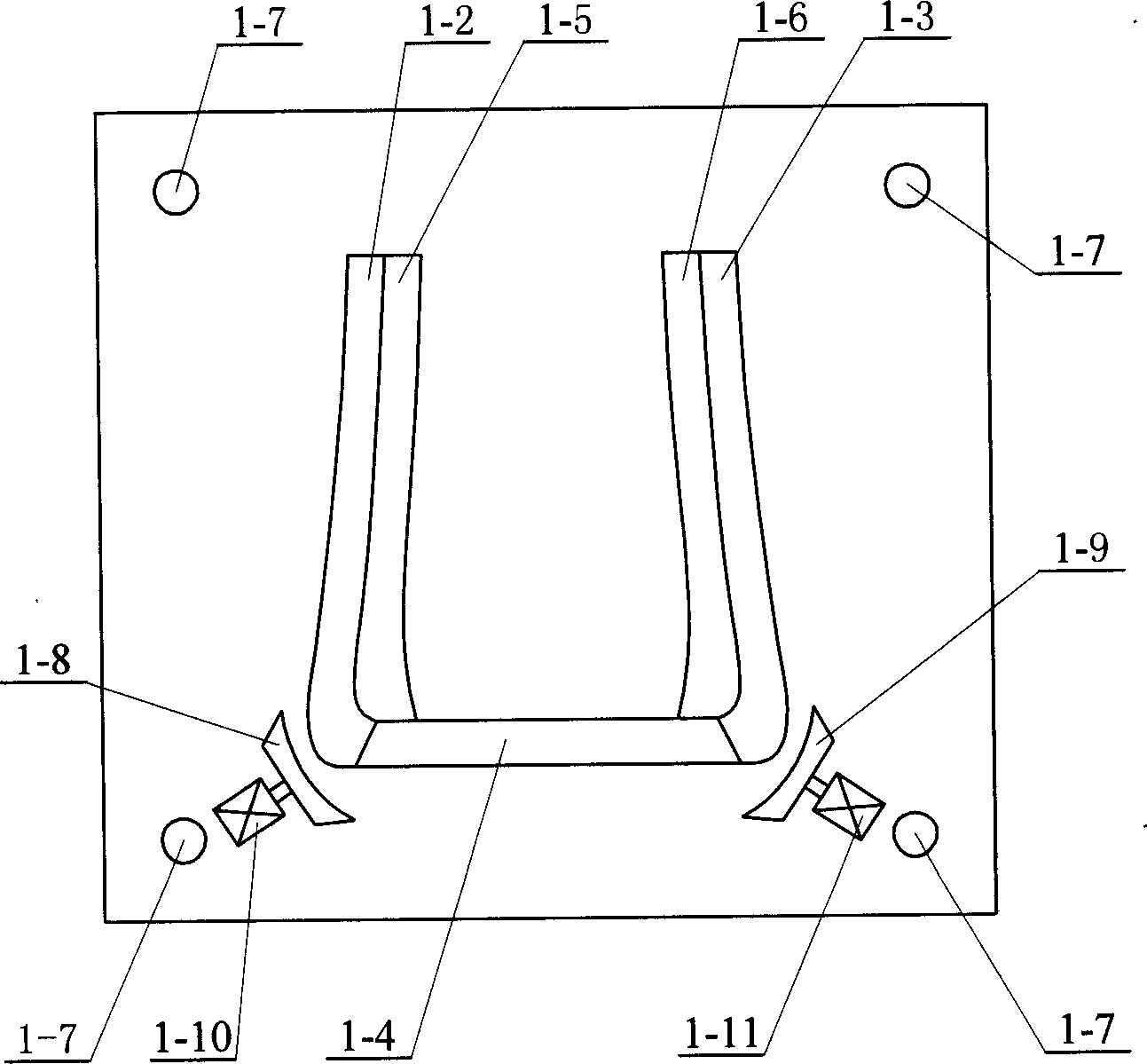
[0006] Specific implementation mode two: the following combination figure 2 This embodiment will be specifically described. The difference between this embodiment and Embodiment 1 is that it also includes a left corner sliding module 1-8, a right corner sliding module 1-9, No. 8 is arranged on the left front side of the connection between the left arm upper module 1-2 and the forearm upper module 1-4, and the left corner sliding module 1-8 is connected to the No. 4 oil cylinder 1-10 fixed on the lower surface of the upper mold bottom plate 1-1 On the piston rod, the right corner sliding module 1-9 is arranged on the right front side of the connection between the right arm upper module 1-3 and the forearm upper module 1-4, and the right corner sliding module 1-9 is connected under the bottom plate 1-1 fixed on the upper mold On the piston rod of No. 5 oil cylinder 1-11 on the surface. Such setting is beneficial to the forming of the tube blank 5 at the corner. Other composi...

specific Embodiment approach 3

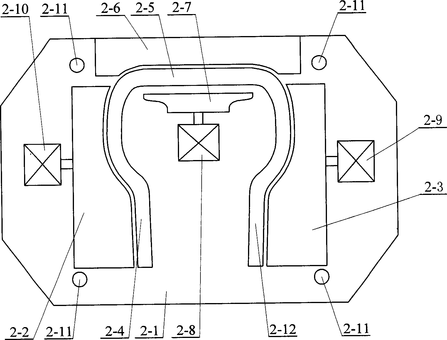
[0007] Specific implementation mode three: the following combination Figure 4 to Figure 6 This embodiment will be specifically described. The difference between this embodiment and Embodiment 1 is that the cross-sectional shapes of the first cavity 6 , the second cavity 7 and the third cavity 8 are rectangular, square, trapezoidal, elliptical, polygonal, or curved. In this embodiment, cavities with various cross-sectional shapes are formed by changing the shapes of the upper, lower, left, and right surfaces participating in the molding, thereby completing the pre-forming of pipes with various cross-sectional shapes.


PUM


Abstract

A preshaping apparatus with internal high pressure for the hollow structure member, such as pipe, is composed of upper mould, lower mould, and press. Said upper mould is fixed to the pressing head of press. The different surfaces of said upper and lower moulds, a movable moulding block and a fixed moulding block can form the first, the second and the third moulding cavities. When said movable moulding block is driven by cylinder and said upper mould is driven by press, the sizes of moulding cavities are changing to form a pipe.

Description

Technical field: [0001] The invention relates to a preforming device specially used for internal high pressure forming of hollow structural parts. Background technique: [0002] In the fields of aircraft, spacecraft and automobiles, reducing the weight of parts and components is one of the trends in technological development. Under this background, internal high pressure forming is an advanced manufacturing technology for manufacturing hollow light-weight structural parts. This technology not only improves the strength and stiffness of the formed parts, but also saves materials and reduces costs. The basic process of this technology is: first put the tube blank in the lower mold, then close the upper mold, seal the two ends of the tube with a horizontal punch, and fill the tube blank with liquid. During the pressurization and bulging process, The punches at both ends push the material inward at the same time, so that under the combined action of internal pressure and axial ...

Claims


Application Information

Patent Timeline
Patent Type & Authority Applications(China)
IPC IPC(8): B21D26/033B21D26/047B21D37/10
Inventor 苑世剑韩聪
Owner 哈尔滨工达海卓智能成形科技有限公司
Why Eureka
Try Eureka