Bulk material pump feeder

A technology for loose materials and feed pumps, applied in the direction of conveying bulk materials, pumps, pump components, etc., can solve the problems of affecting accuracy and feeding performance, reducing and slowing down equipment operation speed, material jamming, etc.

Inactive Publication Date: 2005-07-27
K TRON TECH INC
View PDF2 Cites 10 Cited by
  • Summary
  • Abstract
  • Description
  • Claims
  • Application Information

AI Technical Summary

Problems solved by technology

[0005] While this unfavorable jamming effect may be infrequent and often varies with the type of material being processed, when it occurs, even temporarily, it can affect accuracy and feed performance to an unacceptable level
Because of the tendency of equipment to stop due to failure, this failure shutdown is

Method used


Image

  • Bulk material pump feeder
  • Bulk material pump feeder
  • Bulk material pump feeder

Examples


Embodiment Construction

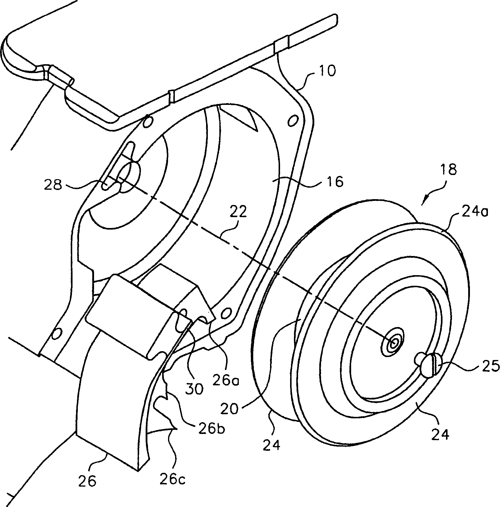
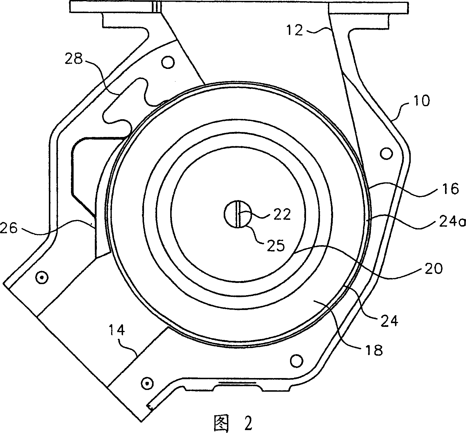
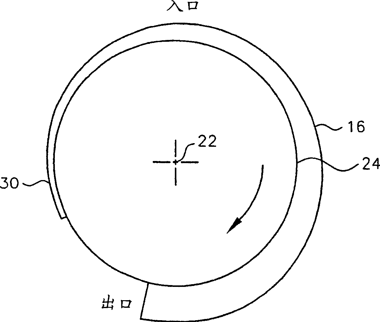
[0013] refer to figure 1 and 2, a bulk material feed pump constructed in accordance with the present invention includes a housing 10 having an inlet 12 , an outlet 14 and an inner wall 16 extending from the inlet 12 to the outlet 14 . A bulk material feed pump constructed in accordance with the present invention is substantially similar in construction and operation to the devices described and illustrated in US Patent Nos. 5,051,041 and 5,355,993, the entire contents of which are incorporated herein by reference.

[0014] figure 1 The bulk material feed pump shown in and 2 also has a drive rotor 18 having a hub 20 rotatable about an axis of rotation 22 and a pair of drive discs 24 which are directed away from the hub towards the housing 10 inner wall extension. For the embodiment of the invention being described, the hub 20 and drive disc 24 are formed as one unit. To facilitate delivery of bulk material from the inlet 12 of the housing 10 to the outlet 14 of the housing, ...


PUM


Abstract

A bulk materials pump feeder having a housing and a rotatable drive rotor mounted in the housing for transferring material introduced into the housing through an inlet to an outlet for discharge of the material from the housing. The drive rotor has a hub and a plurality of drive discs extending away from the hub toward an inner wall of the housing. To reduce the tendency of material passing through the housing to wedge between the inner wall of the housing and the circumferential edges of the drive discs, the distance between the circumferential edges of the drive discs and the inner wall of the housing increases from the inlet of the housing to the outlet of the housing in the direction of rotation of the drive rotor.

Description

technical field [0001] The present invention relates generally to material handling equipment and more particularly to a material handling equipment pump feeder for feeding bulk material. Background technique [0002] In some bulk material handling equipment, such as those described and illustrated in US Pat. One or more drive discs mounted on or integral with the rotary shaft. In the past, this type of equipment has been used to convey uniform or non-uniform grade coal or other friable materials. Typically, the drive system for such equipment transmits high torque at low speeds. [0003] Since this equipment is adapted to handle different materials supplied in different sizes, problems arise which have not been encountered before. One of the most important problems is due to the material being processed being stuck between the rotating drive rotor and the housing or stationary parts mounted on the housing, due to the smaller size of the equipment, more difficult to handl...

Claims


Application Information

Patent Timeline
IPC IPC(8): B65G31/04B65G53/42F04D7/04F04D29/22F04D29/42
CPCF04D7/045F04D29/2266B65G31/04F04D29/426B65G53/46F04D23/00F04D17/16B65G53/42
Inventor 蒂莫西·R·贝尔詹姆斯·T·福利
Owner K TRON TECH INC
Why Eureka
Try Eureka