Clean oil container

A container and oil-holding technology, which is applied in the field of containers, can solve the problem of the surface of the pot body being polluted by spilled oil, and achieve the effect of being easy to use

Inactive Publication Date: 2005-08-03
刘驰
View PDF0 Cites 1 Cited by
  • Summary
  • Abstract
  • Description
  • Claims
  • Application Information

AI Technical Summary

Problems solved by technology

[0003] The purpose of the present invention is to provide a clean oil container to overcome the problem that the surface of the pot body is polluted by spilled oil

Method used


Image

  • Clean oil container
  • Clean oil container
  • Clean oil container

Examples


Embodiment Construction

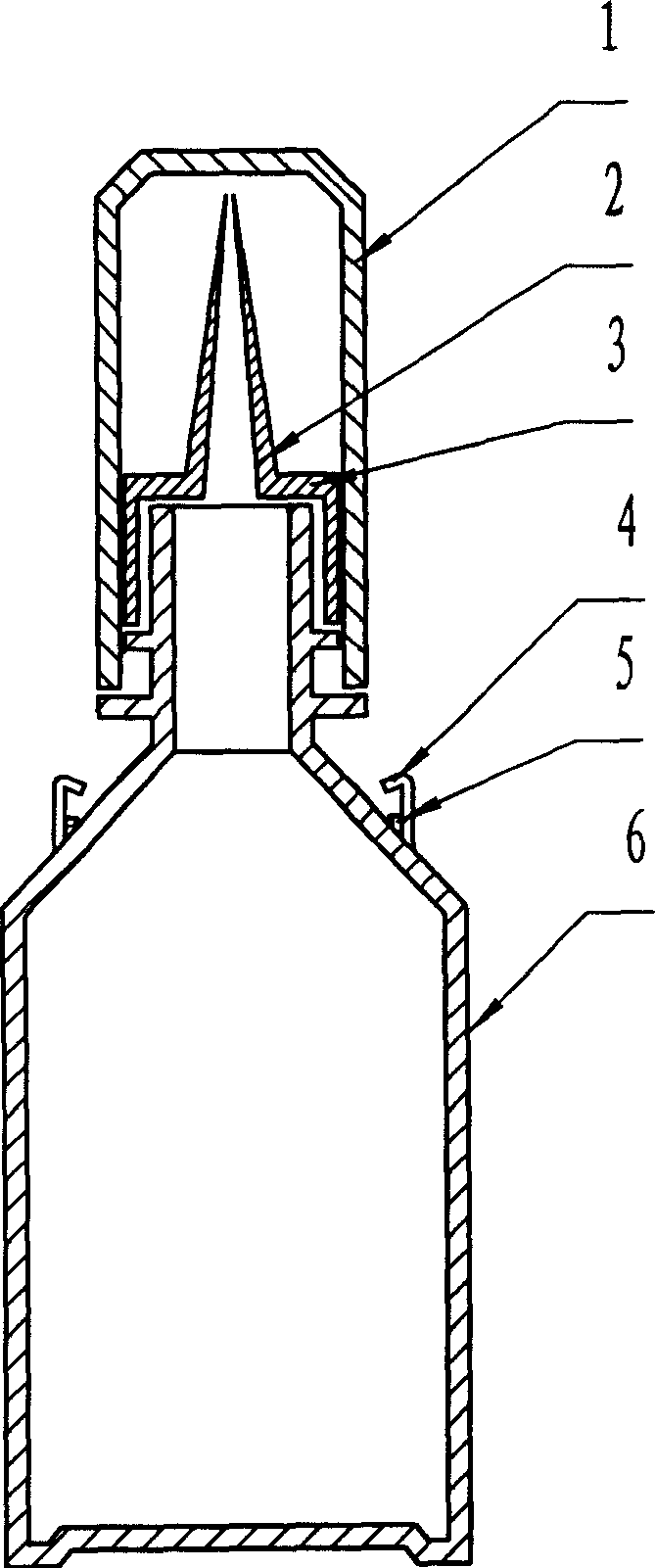
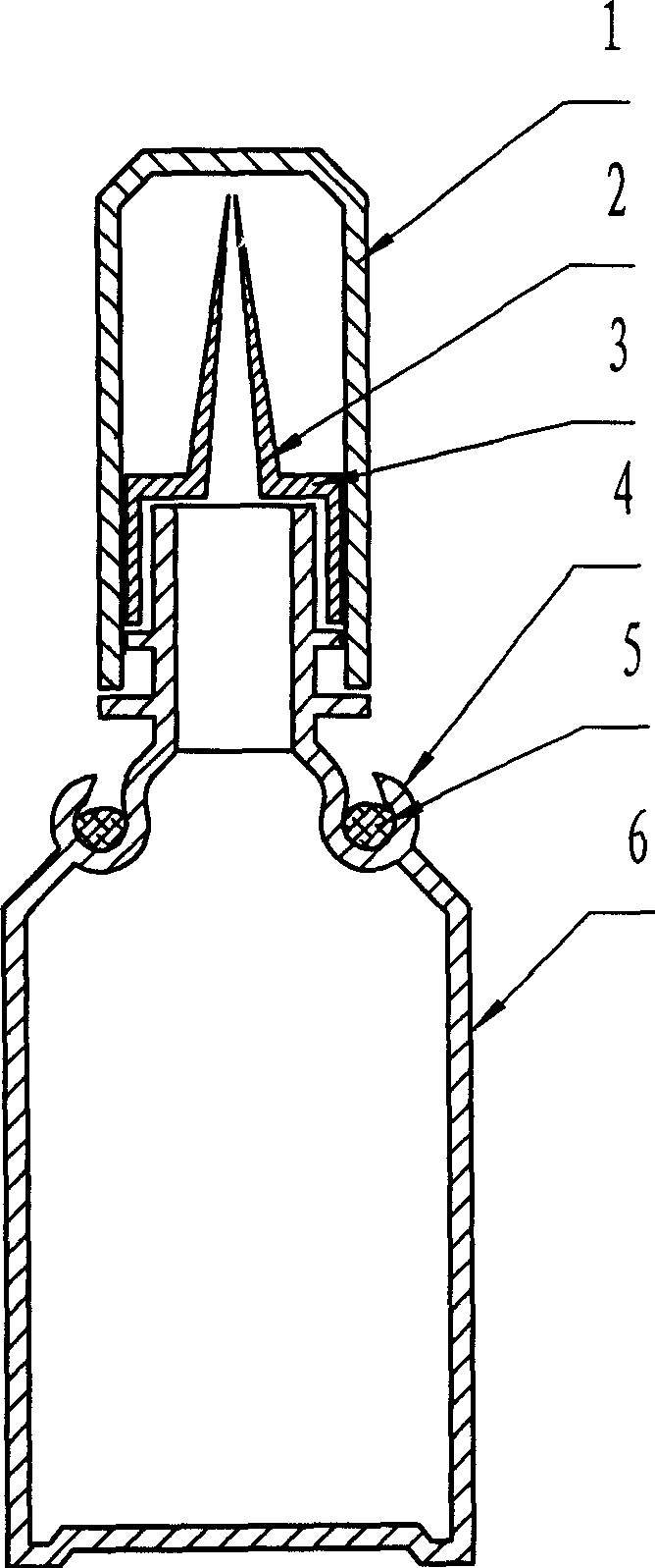
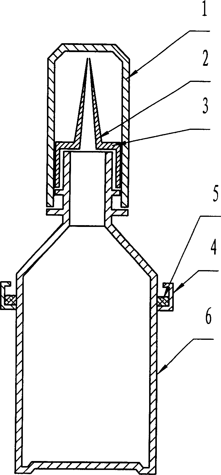
[0016] Such as figure 1 The structure of the oiler shown. It consists of a pot body 6, a pot cover 3, an oil storage tank 4, a sponge ring 5 and a dust cover 1.

[0017] The lower end of the kettle body is cylindrical and the upper end shrinks into a conical shape. The kettle body 6 is threadedly connected with the kettle cover 3 . Described pot lid 3 has screw thread inside, is used for being tightened with kettle body 6, prevents from leaking oil, and the upper end of pot lid 3 is oil nipple 2. The pot lid 3 and the oil nozzle 2 are integrally injection molded. Kettle body 6 top is positioned at the bottom of conical body and is provided with an annular oil storage tank 4, and the opening direction of this oil storage tank 4 is upwards and is positioned at kettle body 6 body wall outsides, and oil storage tank 4 open ends shrink into a hook shape to the kettle body center. In order to facilitate the absorption of oil in the oil storage tank, a sponge ring 5 is arranged i...


PUM


Abstract

The present invention provides a clean oil container, and aims at solving the problem of oil overflow. The clean oil container consists of container body and matched container cap, and features that the container body has one outer ring oil sump in the upper part and the oil sump has upward opening and hooked edge. The oil container can maintain clean surface for convenient use, and may be used in holding lubricant oil and edible oil.

Description

technical field [0001] The invention relates to a container used for oil storage and refueling, in particular to a clean oil container. technical background [0002] For vehicles such as bicycles, battery cars, and motorcycles, as well as mechanically rotating household appliances such as electric fans and washing machines, or agricultural machinery, these appliances need to be regularly maintained with lubricating oil to reduce resistance and mechanical wear and prolong service life. The refueling container is indispensable for every family. Some families use empty wine bottles and beverage bottles to store lubricating oil. The disadvantage is that it is difficult to fill and waste lubricating oil. The disadvantage of the pot is that the surface of the pot body is easily polluted by spilled oil (the same is true for household cooking oil bottles), and it is very inconvenient to get your hands dirty every time you use it. Contents of the invention [0003] The purpose of ...

Claims


Application Information

Patent Timeline
Patent Type & Authority Applications(China)
IPC IPC(8): B65D1/00B65D23/06
Inventor 刘驰关梦瑶刘福启
Owner 刘驰
Why Eureka
Try Eureka