Variable-polarization microstrip reflectarray antenna

A reflectarray antenna and reflectarray technology, applied in antennas, antenna arrays, electrical components, etc., can solve problems such as inability to realize polarization transformation, complex structure, and limited array period size, and achieve simple structure, reduced gain, and elimination of The effect of the occlusion effect

Inactive Publication Date: 2005-08-24
SOUTHEAST UNIV
View PDF0 Cites 22 Cited by
  • Summary
  • Abstract
  • Description
  • Claims
  • Application Information

AI Technical Summary

Problems solved by technology

[0002] At present, most of the microstrip reflectarray antennas cannot realize polarization transformation. There is only a kind of reflectarray that adopts dual-polarized square patch array elements of 'linear polarization-orthogonal linear polarization transformation', and each patch is Contains an additional feeder network that connects the feed ports of two polarizations. The structure is complex and limited by the size of the array period. In principle, it can only realize the function of a narrower frequency band and smaller size orthogonal linear polarization transformation reflectarray.

Method used


Image

  • Variable-polarization microstrip reflectarray antenna
  • Variable-polarization microstrip reflectarray antenna
  • Variable-polarization microstrip reflectarray antenna

Examples


Embodiment 1

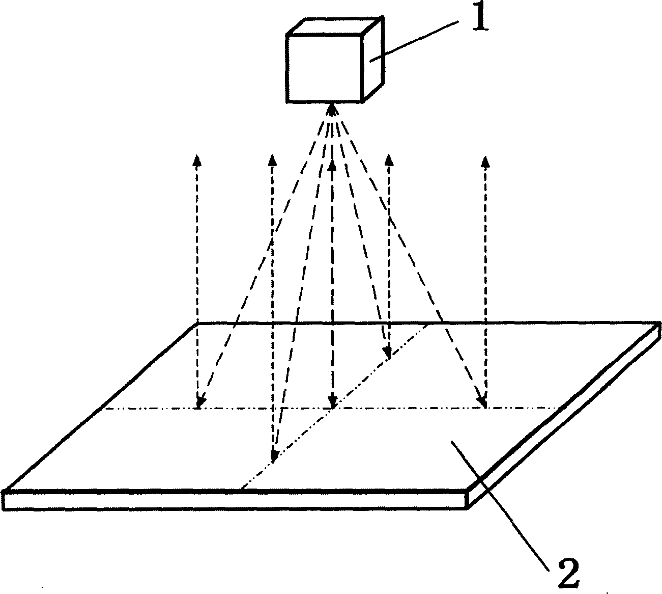
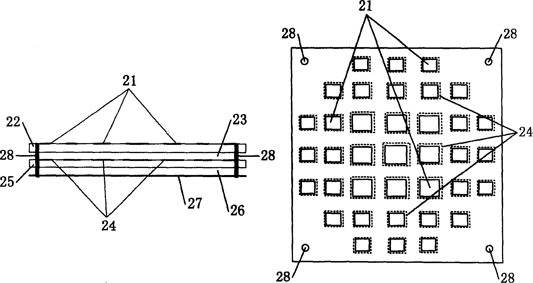
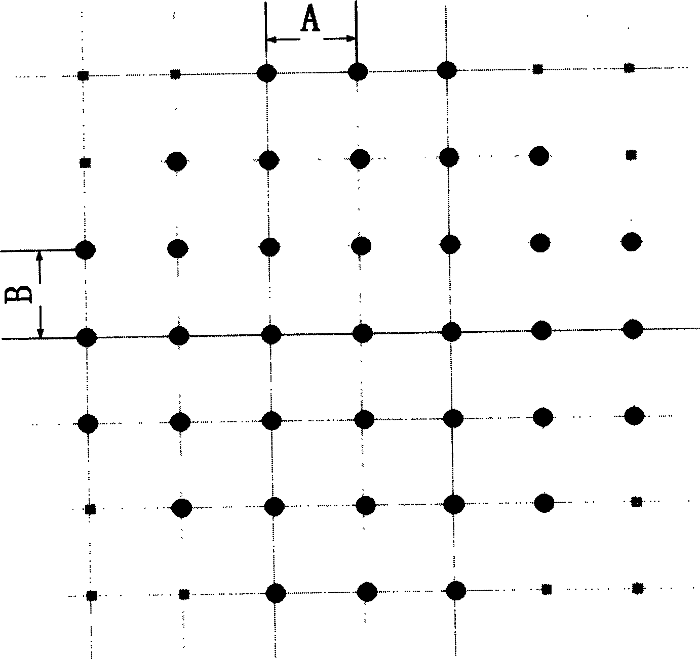
[0018] A polarization-variable microstrip reflectarray antenna capable of polarization conversion, consisting of a feed source 1 and a reflectarray 2, characterized in that the reflectarray 2 consists of an upper dielectric substrate 22, a lower dielectric substrate 25 and a grounded metal plate 27 composition, the lower dielectric substrate 25 is located between the upper dielectric substrate 22 and the grounded metal plate 27, a gap 23 is provided between the upper dielectric substrate 22 and the lower dielectric substrate 25, and the lower dielectric substrate 25 and the grounded metal plate 27 is also provided with a gap 26, an upper rectangular patch 21 is arranged on the upper dielectric substrate 22, and the upper rectangular patch 21 is located on a grid point arranged periodically, and a lower rectangular patch 24 is arranged on the lower dielectric substrate 25. , the lower rectangular patch 24 is located on the grid points arranged periodically, the grid point array ...

Embodiment 2

[0023] Use a medium with a thickness of 0.5mm (ε r =2.2) The substrate and the 37-element patch array with 2mm air gap, the two-dimensional period of the grid lattice is 18mm, and the similarity ratio of the size of the upper and lower patch of the same grid point is 0.7. According to the order of the distance between the center of the patch and the center of the array from small to large, the width-to-length ratio of the rectangular patch is {0.91, 0.915, 0.92, 0.90, 0.90, 0.90, 0.87, 0.86}, and the length of the lower rectangular patch (mm) are {14, 13.6, 13.3, 12.7, 12.4, 11.5, 11.1, 10.8} in turn. The design frequency is 10GHz and the working frequency band is 14%. The printed radiator with gradient groove line is used as the linear polarization feed source to realize the transformation from linear polarization to left-handed circular polarization.


PUM


Abstract

A polarization micro-strip reflection antenna, composed of the reflection resource and the mattress reflector. The mattress reflector is made up of the upper and the lower dielectric substrates and the grounded metal board. The lower dielectric substrate is between the upper substrate and the grounded metal board, and there is space between the upper and the lower dielectric substrates, and between the lower dielectric substrate and the grounded metal sheet. Set the upper rectangle sticking sheet on the upper dielectric substrate, and the upper rectangle sticking sheet is on the cycle-arranged lattice points. Set the lower rectangle sticking sheet on the lower dielectric substrate, and the lower rectangle sticking sheet is on the cycle-arranged lattice points. The lattice points array of the upper dielectric substrate superposes that of the lower one, and the two rectangle sticking sheets on the same lattice point have similar shape, the long side and the short side sizes of the rectangle sticking sheets on the same dielectric substrate decrease with the increase of the distance from its lattice point to the central lattice point, the sizes of long and short sides of the lower rectangle sticking sheets are bigger than that of the upper sheets.

Description

technical field [0001] The invention relates to a microstrip antenna, in particular to a variable polarization microstrip reflector array antenna capable of realizing polarization transformation. Background technique [0002] At present, most of the microstrip reflectarray antennas cannot realize polarization transformation. There is only a kind of reflectarray that adopts dual-polarized square patch array elements of 'linear polarization-orthogonal linear polarization transformation', and each patch is The additional feeder network containing the feed ports connecting the two polarizations has a complex structure and is limited by the size of the array period. In principle, it can only realize the function of a narrower frequency band and smaller size orthogonal linear polarization transformation reflectarray. Contents of the invention [0003] The invention provides a variable polarization microstrip reflector a...

Claims


Application Information

Patent Timeline
Patent Type & Authority Applications(China)
IPC IPC(8): H01Q13/08H01Q21/00
Inventor 章文勋吴知航
Owner SOUTHEAST UNIV
Why Eureka
Try Eureka