Self-propelled road milling machine

A road roller, self-propelled technology, applied in the direction of roads, roads, road repairs, etc., can solve problems such as increasing the risk of accidents

Inactive Publication Date: 2005-08-24
WIRTGEN GMBH
View PDF4 Cites 13 Cited by
  • Summary
  • Abstract
  • Description
  • Claims
  • Application Information

AI Technical Summary

Problems solved by technology

Installation of the split ring may require repeated changes in the rotational position of the roller base, for example 180°, increasing the risk of accidents

Method used


Image

  • Self-propelled road milling machine
  • Self-propelled road milling machine
  • Self-propelled road milling machine

Examples


Embodiment Construction

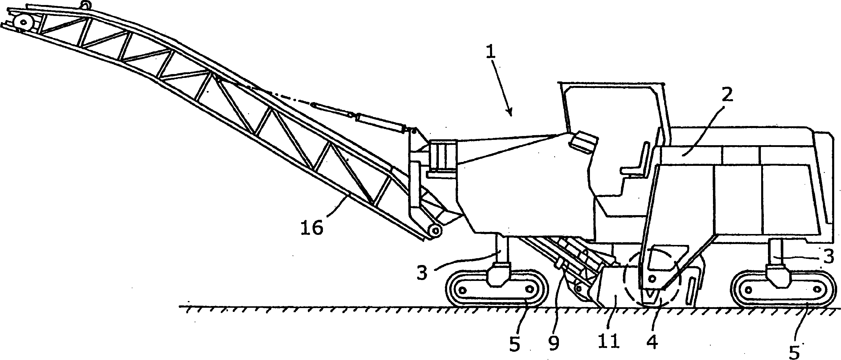
[0037] exist figure 1Shown is a road roller 1 which can employ the quick change roller tube system described below. In general, a road roller comprises a road roller frame 2 on which an internal combustion engine and a driving platform are mounted. The self-propelled road roller comprises a height-adjustable lifting column 3 mounted on a frame 2, on which support wheels or chain drive gears 5 are mounted.

[0038] The lamination rolls 4 are located in a lamination roll box 11 below the frame 2 , the sides of which are limited by side plates 12 , 13 . In a known manner, the material processed by the calender rollers 4 falls on a first conveyor belt 9 and is transported to a second height-adjustable and rotatable conveyor belt 16 .

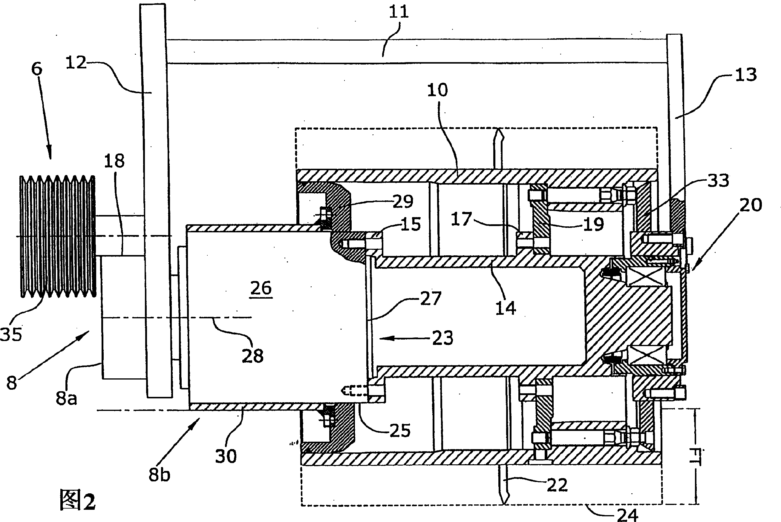
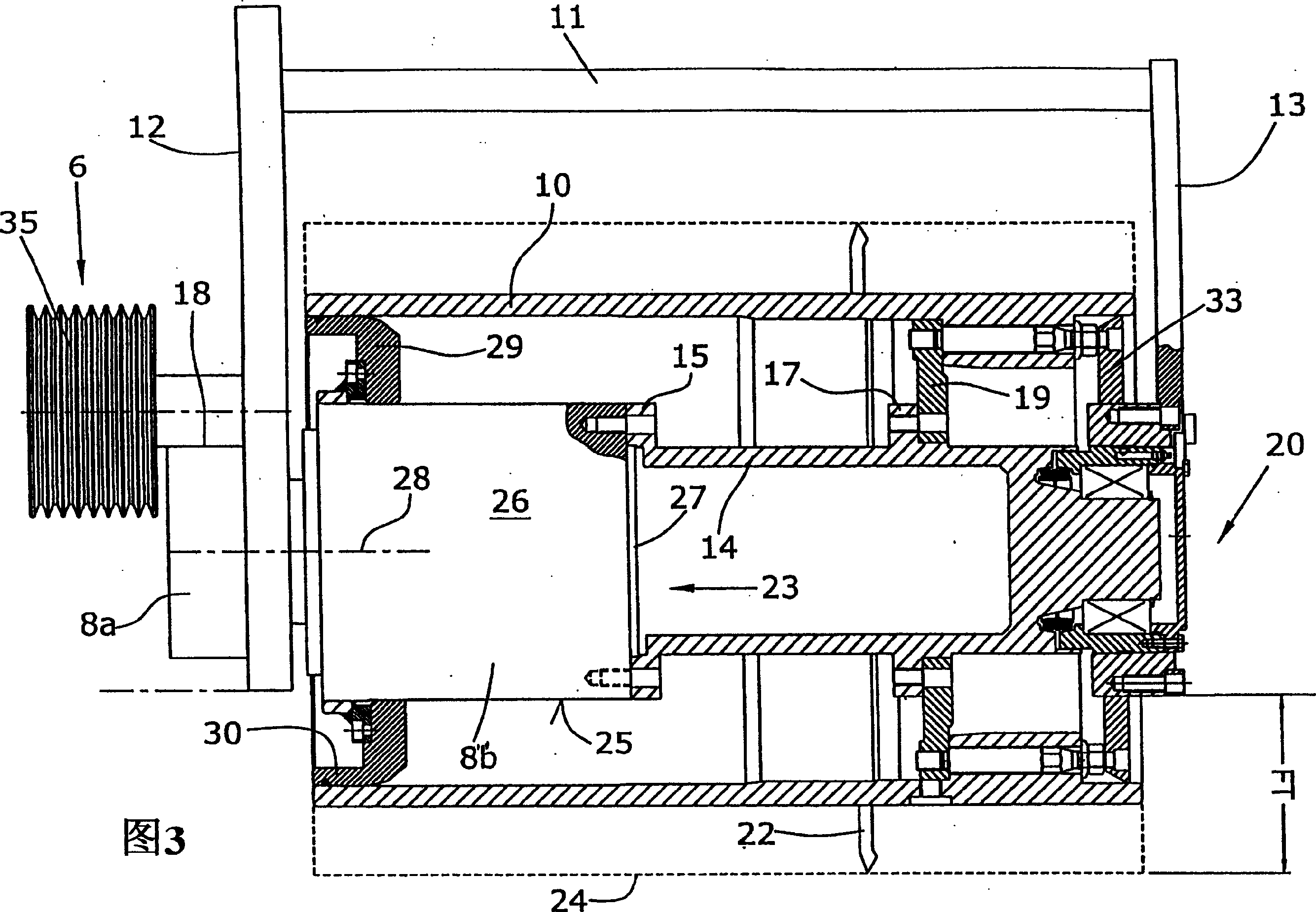
[0039] The lamination roller 4 is rotatably supported between the side plates 12, 13 of the lamination roll box 11, which extend perpendicularly to the axis of the lamination roll and are supported on the input side side plate 12 by the drive devi...


PUM


Abstract

The invention relates to a self-propelled road milling machine comprising a machine chassis (2), inside of which a milling roll (4) is rotationally mounted between lateral plates (12, 13) that are orthogonal to the axis of the milling roll (4). This milling roll (4), which has a roll base body (14) and a milling tube (10), can be driven via a drive device (6), which is mounted on the exterior of the input-side lateral plate (12), and via a reduction gear unit (8). The lateral plate (13), which is provided for exchanging alternatively mountable milling tubes (10) of different milling widths and which is situated opposite the input-side lateral plate (12), can be easily detached and defines the null side of the machine (1) against which the face of the milling roll (4) rests in an approximately flush manner. In order to enable a milling that is near the edge, the invention provides that the reduction gear unit (8) is mounted on the input side, and that the reduction gear unit (8) comprises an output element, which is mounted on the interior of the input-side lateral plate (12) and whose outer surface (25) forms a seat for milling tube elements that can be slid thereon from the null side. In addition, the invention provides that the roll base body (14) is coupled to the reduction gear unit (8) via the free face (23) of the output element without preventing the milling tube elements from being slid on.

Description

technical field [0001] The invention relates to a self-propelled road roller according to the preamble of claim 1 . Background technique [0002] Due to the different construction site environments and the different rolling tasks, it is often necessary to adapt the rolling tools of the road roller to specific tasks. For example, in order to achieve a particular road surface roughness, lapping rollers or other tooling equipment with a particular track distance of the lapping tool is required. In another application only a certain pavement width needs to be completed and thus a lamination roller with a specific working width is required. [0003] Usually, a specific roller or machine that has to be used in such an environment must have rollers adapted to the task, however, changing rollers is currently very cumbersome and requires special auxiliary equipment for mounting and dismounting the rollers respectively . [0004] Adapting rolling tools to different needs is known i...

Claims


Application Information

Patent Timeline
Patent Type & Authority Applications(China)
IPC IPC(8): E01C23/12E01C23/088
CPCE01C23/088
Inventor 贝恩德·赫尔赫伯特·莱冈特·哈恩
Owner WIRTGEN GMBH
Why Eureka
Try Eureka