Driving method for field emission displays

A driving method and field emission technology, applied in the direction of static indicators, instruments, etc., can solve the problems of higher driving voltage requirements and the inability to achieve high-quality video display, shorten the research cycle, reduce development and manufacturing costs, high resolution effects

Inactive Publication Date: 2005-09-14
SOUTHEAST UNIV
View PDF0 Cites 4 Cited by
  • Summary
  • Abstract
  • Description
  • Claims
  • Application Information

AI Technical Summary

Problems solved by technology

However, there is no specific driving method for field emission displays; especially for field emission displays that are currently suitable for large-area display by screen pri

Method used


Image

  • Driving method for field emission displays
  • Driving method for field emission displays
  • Driving method for field emission displays

Examples


Embodiment Construction

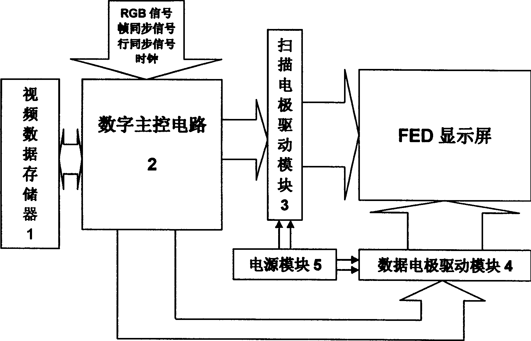
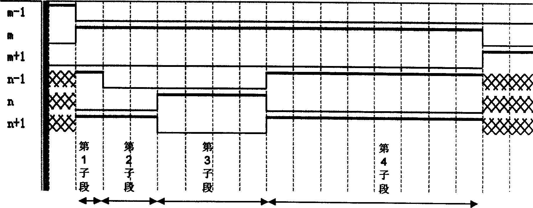
[0021] The driving method provided by the present invention includes a video data storage method, timing control for grayscale realization, a high-voltage driving module and a voltage suspension method. And an adjustment scheme that conforms to the performance of the display device and the visual characteristics of the human eye is given. The driving method is based on the 2 b Level gray scale, each row will display time T line according to:

[0022] T line ·2 0 / (2 b -1): T line ·2 1 / (2 b -1): T line ·2 2 / (2 b -1):...:T line ·2 b-1 / (2 b -1)

[0023] The ratio is divided into sub-sections, and the total time length of each sub-section is the display time T of each row line ; The time length of each sub-segment represents a gray level, and the display of the corresponding gray level of the sub-segment is realized through the voltage driving signal applied by the data electrode during the action time of the sub-segment; for the gray levels represented by the su...


PUM


Abstract

A drive method for a field emission display unit relates to a drive method for field emission display units and specific realization program, which is to divide indicating time Tline each line to subsegments in proportion with Tlineíñ20/(2b-1)í†Tlineíñ21/(2b-1)í†Tlineíñ22/(2b-1)í†í¡í¡í†Tlineíñ2b-1/2b-1 accroding to the 2b grade of gradations of grey to be realized, wherein the overall time of subsegments is the indicating time Tline of each line, while every subsegment time represents a gradation of grey, showing the gradation by a voltage driving signal applied during the time subsegment practiced via a data electrode; beyond the represented gradations of grey, according to the voltage driving signal applied to different subsegments during indicating time each line, the overall time of different subsegments is the showing gradations of grey multiplies the indicating time of the first gradation, so it makes possible to show the proper gradations of grey.

Description

technical field [0001] The invention relates to a driving method and a specific implementation scheme of a field emission display device, belonging to the field of display device manufacturing. Background technique [0002] As an important part of the field emission display device, the driving circuit completes the acquisition of the video image source, and according to the characteristics of the display screen, applies voltage and current waveforms to the display electrodes that meet certain timing requirements, and finally displays the video image on the display screen. Features. If an appropriate driving method is selected, the driving circuit can be simplified, the cost can be reduced, the display effect can be improved, and the performance of the device can be improved. [0003] In today's information society, electronic display devices are becoming more and more important. In order to meet the diverse needs of the ever-growing information society, high-performance, n...

Claims


Application Information

Patent Timeline
IPC IPC(8): G09G3/20G09G3/30
Inventor 雷威张宇宁马晓燕宗耿张晓兵
Owner SOUTHEAST UNIV
Why Eureka
Try Eureka