Thermal-interface material and production thereof

一种热界面材料、制造方法的技术,应用在冷却/通风/加热改造、用于材料和表面科学的纳米技术、薄料处理等方向,能够解决热界面材料导热系数降低、均匀性难得到保证、不利器件等问题,达到增大直接接触面积、降低体积及重量、导热一致均匀的效果

Active Publication Date: 2005-10-12
TSINGHUA UNIV +1
View PDF2 Cites 13 Cited by
  • Summary
  • Abstract
  • Description
  • Claims
  • Application Information

AI Technical Summary

Problems solved by technology

[0006] U.S. Patent No. 6,407,922 discloses a thermal interface material that utilizes the thermal conductivity of carbon nanotubes. It incorporates carbon nanotubes into a matrix material and then forms a thermal interface material by molding. The two components of the thermal interface material The area of ​​the heat conduction surface is not equal, and the area of ​​the heat conduction surface in contact with the heat sink is larger than the area of ​​the heat conduction surface in contact with the heat source, which can help the heat sink to dissipate heat, but the thermal interface material made by this method still has the following shortcomings, its First, it is difficult to make the thickness of the thermal interface material thinner by molding. Therefore, on the one hand, it leads to a decrease in the thermal conductivity of the thermal interface material, and on the other hand, it increases the volume of the thermal interface material, which is not conducive to the development of devices in the direction of miniaturization Second, the thermal interface material made by this method has disordered arrangement of carbon nanotubes in the matrix material, and it is difficult to ensure the uniformity of its distribution in the matrix material. , so the uniformity of heat conduction is also affected, and the advantages of longitudinal heat conduction of carbon nanotubes are not fully utilized, which affects the thermal conductivity of thermal interface materials

Method used


Image

  • Thermal-interface material and production thereof
  • Thermal-interface material and production thereof
  • Thermal-interface material and production thereof

Examples


Embodiment Construction

[0025] The present invention will be described in detail below in conjunction with the accompanying drawings and specific embodiments.

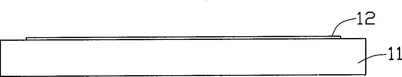
[0026] see figure 1 with figure 2 Firstly, a catalyst thin film 12 is uniformly formed on a substrate 11, and the formation of the catalyst thin film 12 can be accomplished by thermal deposition, electron beam deposition or sputtering. The material of the substrate 11 can be glass, quartz, silicon or alumina. In this embodiment, porous silicon is used, and there is a porous layer on its surface, and the diameter of the pores is extremely small, generally less than 3 nanometers. The catalyst film 12 is made of iron, or other materials, such as gallium nitride, cobalt, nickel and alloys thereof.

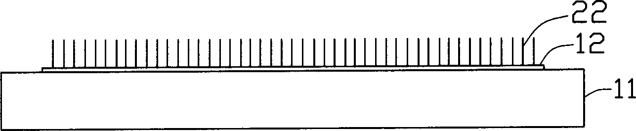
[0027] Then, the catalyst film 12 is oxidized to form catalyst particles (not shown), and then the substrate 11 distributed with catalyst particles is put into a reaction furnace (not shown), and carbon source gas is introduced at 700-1000 degrees...


PUM

PropertyMeasurementUnit
viscosity indexaaaaaaaaaa
diameteraaaaaaaaaa

Abstract

The invention comprises high molecular material and multi carbon nanotubes distributed in the high molecular materials. The thermal interface material forms first surface and second surface. The carbon nanotubes have opening at its both ends and is evenly distributed in the high molecular material, and extends into two surfaces along the first and second surface of thermal interface material. The invention also offers manufacturing method for the thermal interface material. It includes following steps: provides a carbon nanotube array that is soaked in fusion high molecule; solidifies the high molecule to generate high molecule composite material with carbon nanotube distribution; cuts the high molecule composite material to form the thermal interface material.

Description

【Technical field】 [0001] The invention relates to a thermal interface material and a manufacturing method thereof, in particular to a thermal interface material using carbon nanotubes for heat conduction and a manufacturing method thereof. 【Background technique】 [0002] In recent years, with the rapid development of the integration process of semiconductor devices, the degree of integration of semiconductor devices has become higher and higher, while the volume of devices has become smaller and smaller, and its heat dissipation has become an increasingly important issue. The requirements are also getting higher and higher. In order to meet these needs, various heat dissipation methods have been widely used, such as fan heat dissipation, water cooling auxiliary heat dissipation and heat pipe heat dissipation, etc., and a certain heat dissipation effect has been achieved. However, due to the uneven contact interface between the heat sink and the semiconductor integrated devic...

Claims


Application Information

Patent Timeline
Patent Type & Authority Applications(China)
IPC IPC(8): H01L23/36H01L23/373H01L23/42H05K7/20
CPCB82Y10/00H01L23/3733Y10S977/742H01L23/42H01L23/373B82Y30/00H01L2924/0002Y10T428/30Y10T428/29Y10T428/2918Y10T428/2927H01L2924/00
Inventor 黄华刘长洪范守善
Owner TSINGHUA UNIV
Why Eureka
Try Eureka