Thermal interface material producing method

A technology of thermal interface materials and phase change materials, applied in heat exchange materials, chemical instruments and methods, metal material coating technology, etc., can solve the problems of increased thermal resistance and unsatisfactory thermal conductivity of thermal interface materials, and achieve increased Flexibility, increased thermal conductivity, and good thermal conductivity

Active Publication Date: 2006-10-18
TSINGHUA UNIV +1
View PDF0 Cites 19 Cited by
  • Summary
  • Abstract
  • Description
  • Claims
  • Application Information

AI Technical Summary

Problems solved by technology

Therefore, there is a layer of polymer material with relatively high thermal resistance between the thermal conduction path formed by carbon nanotubes and the thermal contact surface, which leads to an increase in the thermal resistance of the entire thermal interface material and unsatisfactory thermal conductivity.

Method used


Image

  • Thermal interface material producing method
  • Thermal interface material producing method
  • Thermal interface material producing method

Examples


Embodiment Construction

[0027] The technical solution will be further described in detail below in conjunction with the accompanying drawings.

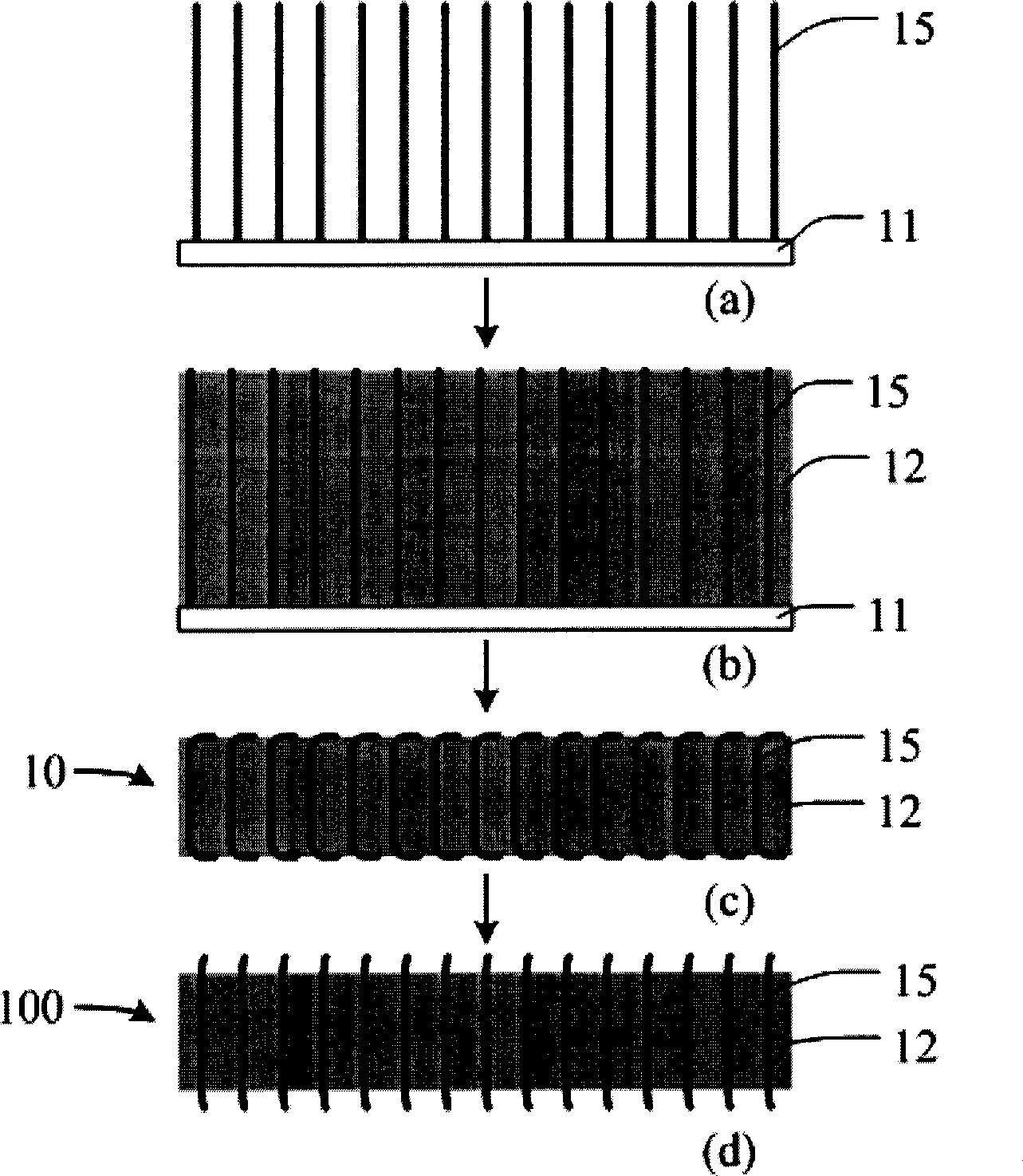
[0028] see figure 1 , the technical solution provides a method for preparing a thermal interface material 100, which includes the following steps:

[0029] Step (a), provide a carbon nanotube array 15; Step (b), fill the gap of described carbon nanotube array 15 with phase change material 12, form composite phase change material; Step (c), along with described carbon Cutting the composite phase change material in the direction where the nanotube arrays intersect to form a slice 10 of predetermined thickness; step (d), heating the slice 10 to above the phase transition temperature of the phase change material 12, so that the carbon nanotubes After the two ends of the tube array 15 expose the phase change material 12 , the slice 10 is cooled to form the thermal interface material 100 .

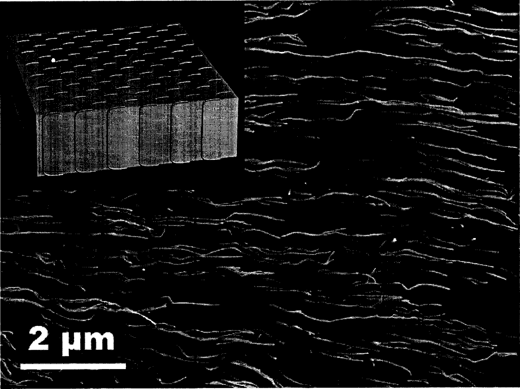
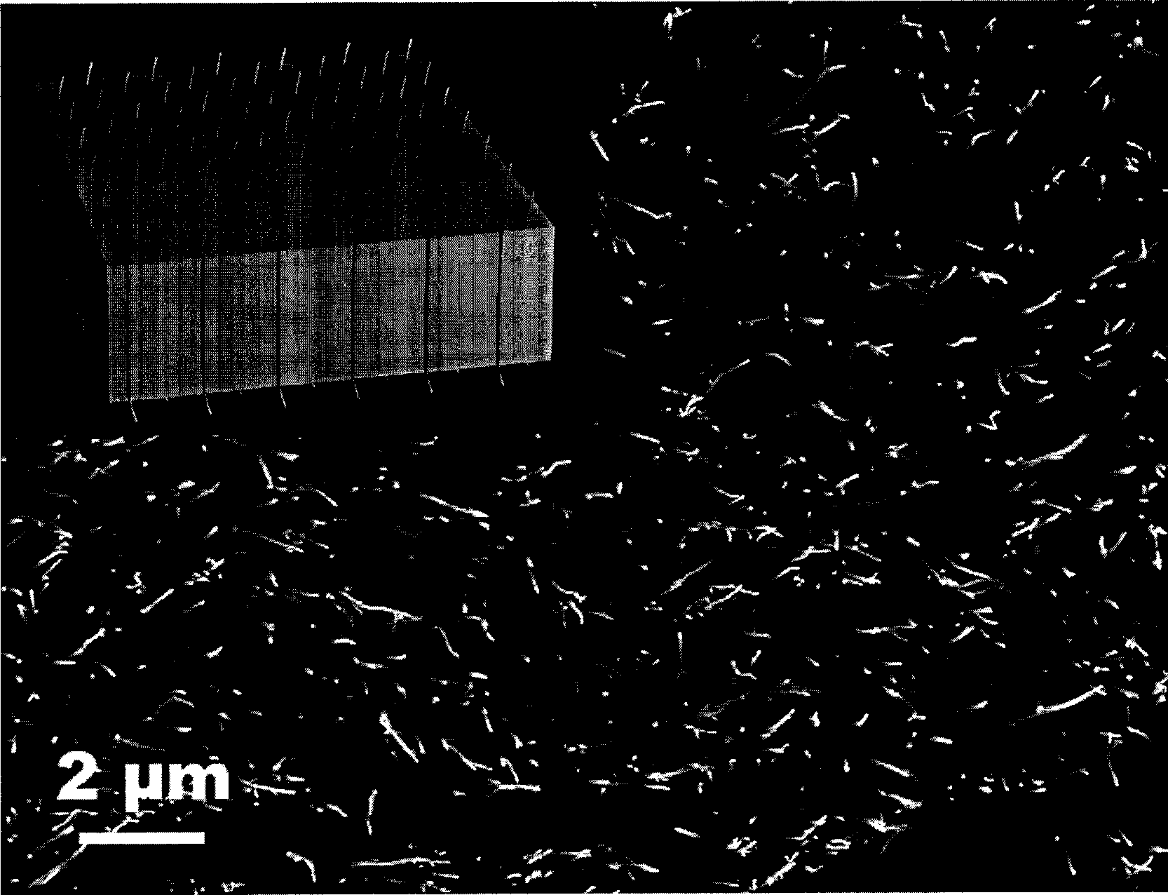
[0030] Please also refer to Figure 1 to Figure 3 , each step of the t...


PUM

PropertyMeasurementUnit
thicknessaaaaaaaaaa
phase transition temperatureaaaaaaaaaa

Abstract

The present invention provides a preparation method of thermal interface material. Said method includes the following steps: providing a carbon nano tube array, using phase change material to fill the gap of the described carbon nano tube array so as to form composite phase change material; along the direction crossed with the described carbon nano tube array cutting the described phase change material into slab with predefined thickness; heating the described composite phase change material slab to the temperature above the phase change temperature of said phase change material, making two ends of the described carbon nano tube array be exposed from said phase change material, then cooling the described composite phase change material slab so as to form thermal interface material.

Description

【Technical field】 [0001] The invention relates to a method for preparing a thermal interface material, in particular to a method for preparing a thermal interface material with carbon nanotubes. 【Background technique】 [0002] In recent years, with the rapid development of the integration process of semiconductor devices, the degree of integration of semiconductor devices has become higher and higher, while the volume of devices has become smaller and smaller, and its heat dissipation has become an increasingly important issue. The requirements are also getting higher and higher. In order to meet these needs, various heat dissipation methods have been widely used, such as fan heat dissipation, water cooling auxiliary heat dissipation and heat pipe heat dissipation, etc., and a certain heat dissipation effect has been achieved. However, due to the uneven contact interface between the heat sink and the semiconductor integrated device, Generally, less than 2% of the area is in...

Claims


Application Information

Patent Timeline
Patent Type & Authority Applications(China)
IPC IPC(8): H01L23/34C09K5/02C23C16/00H01L23/367H01L23/373
CPCB81C1/0069H01L23/373H01L23/427H01L2924/0002Y10S977/842Y10S977/84Y10S977/88Y10S977/753Y10S977/789H01L2924/00
Inventor 黄华吴扬刘长洪范守善
Owner TSINGHUA UNIV
Why Eureka
Try Eureka