Thermal interface material, and its preparing method

A technology of thermal interface materials and polymer materials, applied in heat exchange materials, chemical instruments and methods, thin material processing, etc., can solve the problems of increased thermal resistance of thermal interface materials, small carbon nanotube content, and insufficient heat conduction. , to achieve uniform and uniform heat conduction, reduce contact thermal resistance, and high thermal conductivity.

Active Publication Date: 2007-01-10
TSINGHUA UNIV +1
View PDF0 Cites 15 Cited by
  • Summary
  • Abstract
  • Description
  • Claims
  • Application Information

AI Technical Summary

Problems solved by technology

Therefore, there is a layer of polymer material with relatively high thermal resistance between the thermal conduction path formed by carbon nanotubes and the thermal contact surface, which leads to an increase in the thermal resistance of the entire thermal interface material and unsatisfactory thermal conductivity.
In addition, due to the small content of carbon nanotubes in the thermal interface material, direct contact with the metal still cannot conduct heat sufficiently, and the contact thermal resistance of the thermal interface material is still not ideal

Method used


Image

  • Thermal interface material, and its preparing method
  • Thermal interface material, and its preparing method
  • Thermal interface material, and its preparing method

Examples


Embodiment Construction

[0037] The technical solution will be further described in detail below in conjunction with the accompanying drawings.

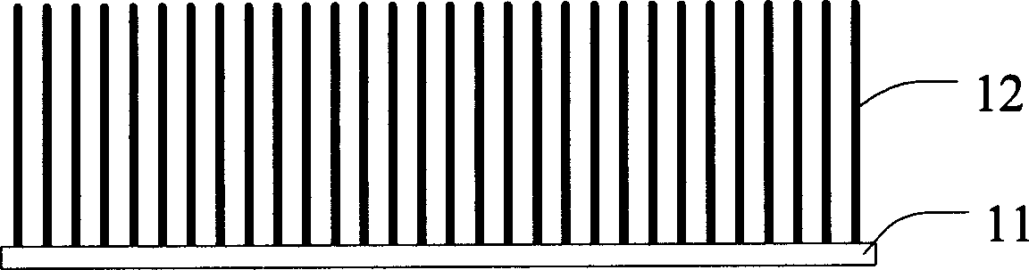
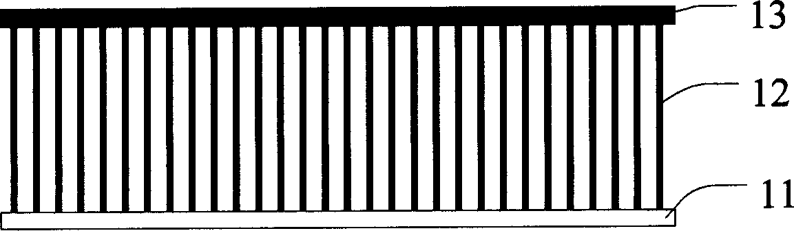
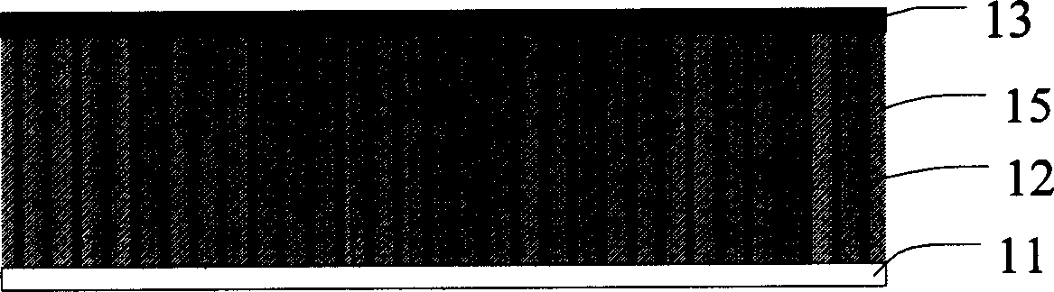
[0038] see Figure 4 , the present embodiment provides a thermal interface material 10, which includes a carbon nanotube array 12, a polymer material 15 filled between the carbon nanotube arrays 12; The heat flow collector 13. see Figure 5 , in another embodiment, the thermal interface material 10 ′ includes two heat flow collectors 13 respectively connected to the two ends of the carbon nanotube array 12 .

[0039] Preferably, the carbon nanotube array 12 is perpendicular to the heat flow collector 13 .

[0040] The material of the heat collector 13 includes metals with good thermal conductivity such as aluminum, copper, gold or silver.

[0041] The heat collector 13 is a metal film, and the metal film 13 in this embodiment is an aluminum film.

[0042] The thickness of the metal film ranges from 1 micron to 10 microns.

[0043] The polymer material ...


PUM

PropertyMeasurementUnit
thicknessaaaaaaaaaa

Abstract

The invention offers heat interface material. It includes many carbon nanometer tubes, polymeric material which is set between the carbon nanometer tubes, at least one heat flow collectors which are connected to the carbon nanometer tube. The heat flow collector can reduce thermal contact resistance and be good for the heat conduction of the carbon nanometer tube. And the invention also offers the manufacturing method of the heat interface material.

Description

【Technical field】 [0001] The invention relates to a thermal interface material, in particular to a thermal interface material with carbon nanotubes and a preparation method thereof. 【Background technique】 [0002] In recent years, with the rapid development of the integration process of semiconductor devices, the degree of integration of semiconductor devices has become higher and higher, while the volume of devices has become smaller and smaller, and its heat dissipation has become an increasingly important issue. The requirements are also getting higher and higher. In order to meet these needs, various heat dissipation methods have been widely used, such as fan heat dissipation, water cooling auxiliary heat dissipation and heat pipe heat dissipation, etc., and a certain heat dissipation effect has been achieved. However, due to the uneven contact interface between the heat sink and the semiconductor integrated device, Generally, less than 2% of the area is in contact with...

Claims


Application Information

Patent Timeline
Patent Type & Authority Applications(China)
IPC IPC(8): C09K5/00
CPCC09K5/14Y10S977/742H01L2924/0002Y10T428/30H01L2924/00
Inventor 吴扬黄华刘长洪范守善
Owner TSINGHUA UNIV
Why Eureka
Try Eureka