Support pin identifying method and device, screen printer and surface installation machine

A technology of identification device and identification method, which is applied in the direction of screen printing machine, printing machine, rotary printing machine, etc., can solve the problems of poor efficiency and time-consuming, and achieve the effect of improving production efficiency and efficient identification processing

Active Publication Date: 2005-10-12
YAMAHA MOTOR CO LTD
View PDF1 Cites 7 Cited by
  • Summary
  • Abstract
  • Description
  • Claims
  • Application Information

AI Technical Summary

Problems solved by technology

[0006] However, in the conventional device disclosed in the above-mentioned Patent Document 1, since a substrate recognition camera with a narrow field of view that captures images of tiny marks (fiducial marks) marked on the substrate is directly used to align the positioning holes on the support table The image recognition of support pins is time-consuming and inefficient because they are photographed one by one.

Method used


Image

  • Support pin identifying method and device, screen printer and surface installation machine
  • Support pin identifying method and device, screen printer and surface installation machine
  • Support pin identifying method and device, screen printer and surface installation machine

Examples


Embodiment Construction

[0032] An example of the best embodiment of the present invention will now be described with reference to the drawings.

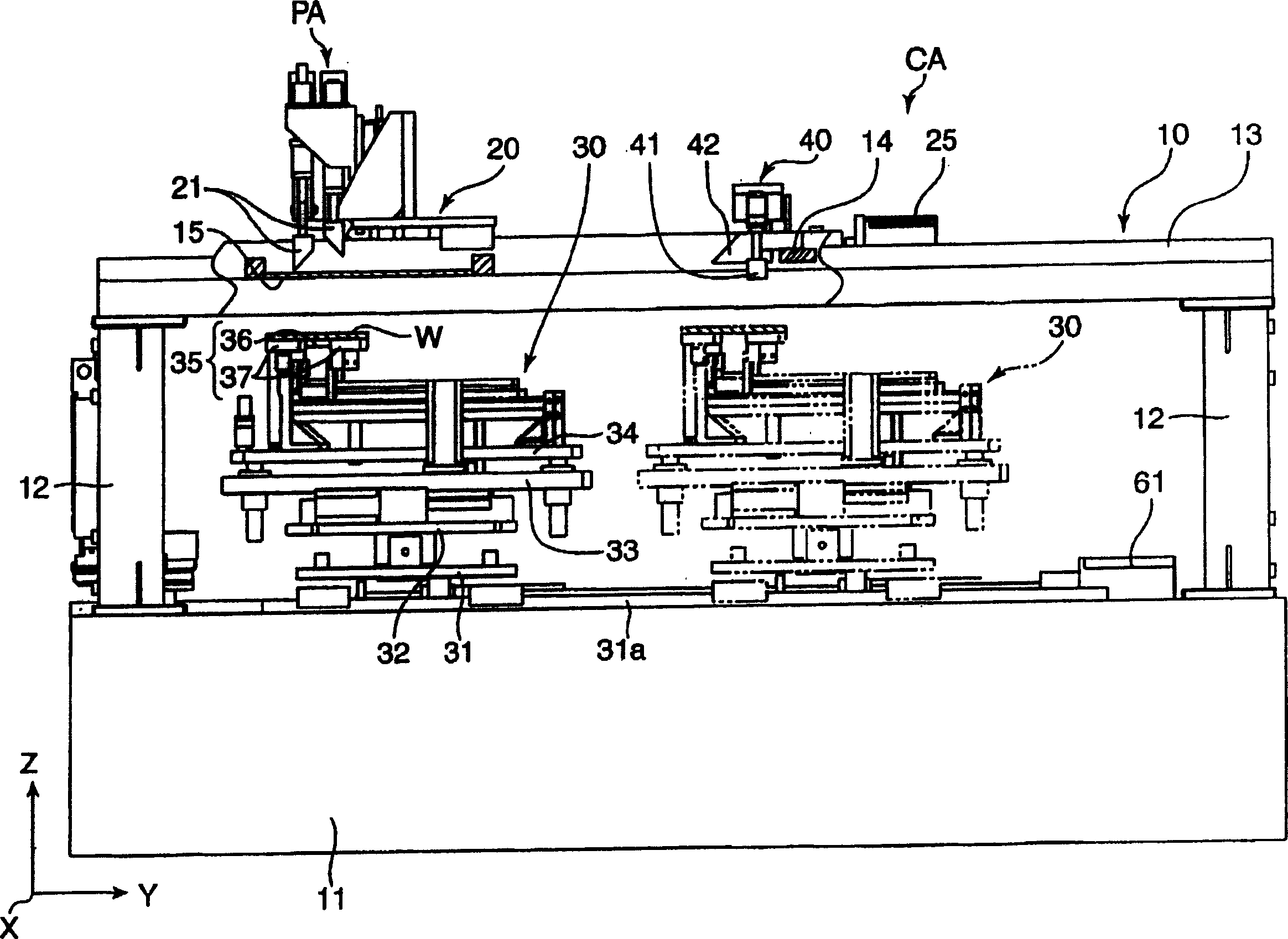
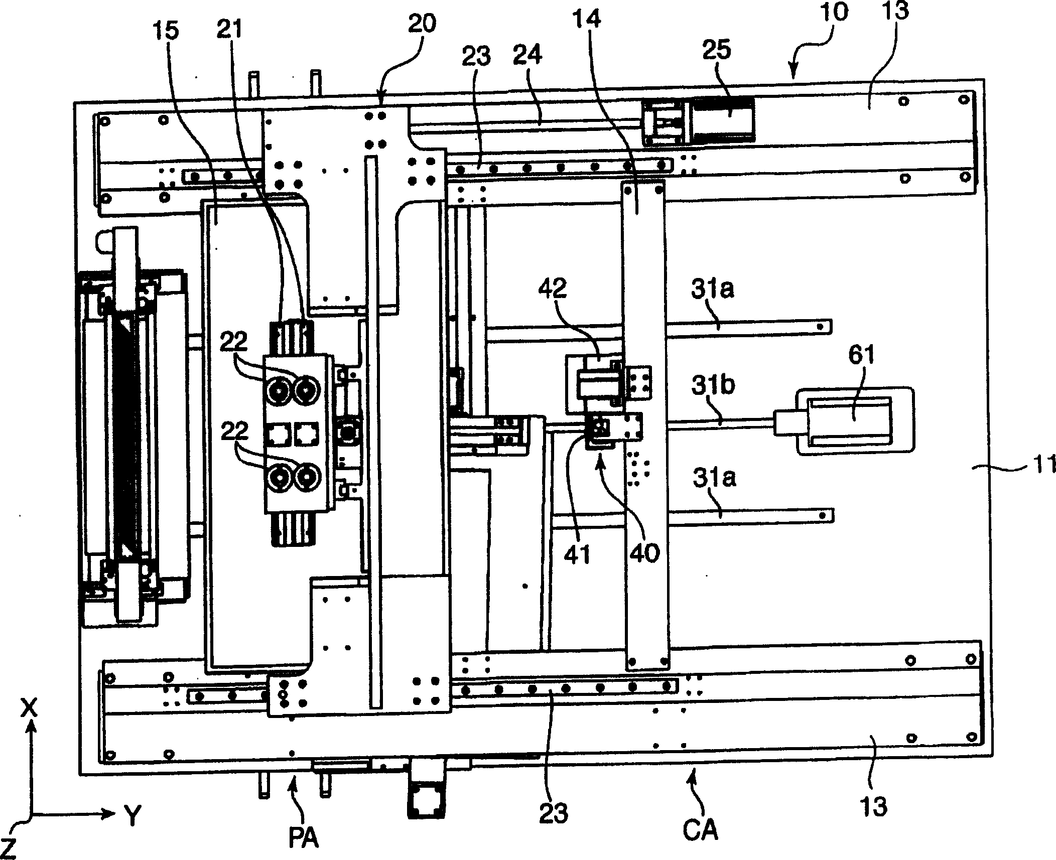
[0033] figure 1 and figure 2 The screen printing device of the present invention (the screen printing device to which the supporting pin identification device of the present invention is applied) is schematically shown, figure 1 is the front view of the printing device, figure 2 is a plan view of the printing device. In order to clarify the direction, the X-axis, Y-axis and Z-axis are shown in the figure.

[0034] The screen printing device shown in these figures (hereinafter simply referred to as the printing device) applies a paste such as cream solder to a predetermined position of the printed circuit board W (hereinafter referred to as the substrate W) and simultaneously applies the paste to the printed circuit board W (hereinafter referred to as the substrate W). A device with an inspection function for checking the state, which has a frame 10, a...


PUM


Abstract

Disclosed is a backup pin recognition method and device. A usage area U0 corresponding to the size of a substrate to be processed in a backup plate 36 is specified, and the usage area U0 is assigned to a plurality of unit areas U1 corresponding to the field of view of a camera that has a wide-angle field of view enough to pick up a plurality of set holes adjoining to each other. The set hole 36a is picked up for each of the unit areas U1 by the camera, and the presence or absence of a backup pin in the respective set holes 36a is discriminated from the image, so as to recognize the arrangement of the backup pins in the used area U0. The invention can improve the productivity of substrates by recognizing the image of a backup pin efficiently.

Description

technical field [0001] The present invention relates to a screen printing device for applying a paste such as cream solder on a substrate such as a printed circuit board, or a surface mounter for mounting components on the substrate, and the substrate is supported by support pins from the back side thereof. The identification method of the support pin and its identification device in the device performing the work, and a screen printing device and a surface mounter having the support pin identification device. Background technique [0002] When mounting electronic components on the front and back of a printed substrate, print (coat paste) on one side of the substrate in the mounting line, mount the electronic components, and then guide the electronic components in a reflow furnace. Then, the substrate is turned over, and then the other side surface of the substrate is printed, installed, conducted and fixed on the installation line. In devices...

Claims


Application Information

Patent Timeline
Patent Type & Authority Applications(China)
IPC IPC(8): B41F15/26G01N21/84G06K9/00H05K3/00H05K3/34H05K13/04H05K13/08
Inventor 尾身幸治
Owner YAMAHA MOTOR CO LTD
Why Eureka
Try Eureka