
A female terminal fitting and connector provided therewith

A technology of terminal joints and connectors, which is applied in the direction of connection, two-part connection device, and parts of the connection device, etc., can solve problems such as reducing insertion force

Inactive Publication Date: 2005-10-19
SUMITOMO WIRING SYST LTD
View PDF0 Cites 21 Cited by
  • Summary
  • Abstract
  • Description
  • Claims
  • Application Information

AI Technical Summary

Problems solved by technology

[0003] On the other hand, in this type of connector, reducing the insertion force when inserting the female terminal fitting into the cavity is a big problem

Method used


Image

  • A female terminal fitting and connector provided therewith
  • A female terminal fitting and connector provided therewith
  • A female terminal fitting and connector provided therewith

Examples


Embodiment Construction

[0043] A preferred embodiment of the present invention will be described below with reference to FIGS. 1 to 11 .

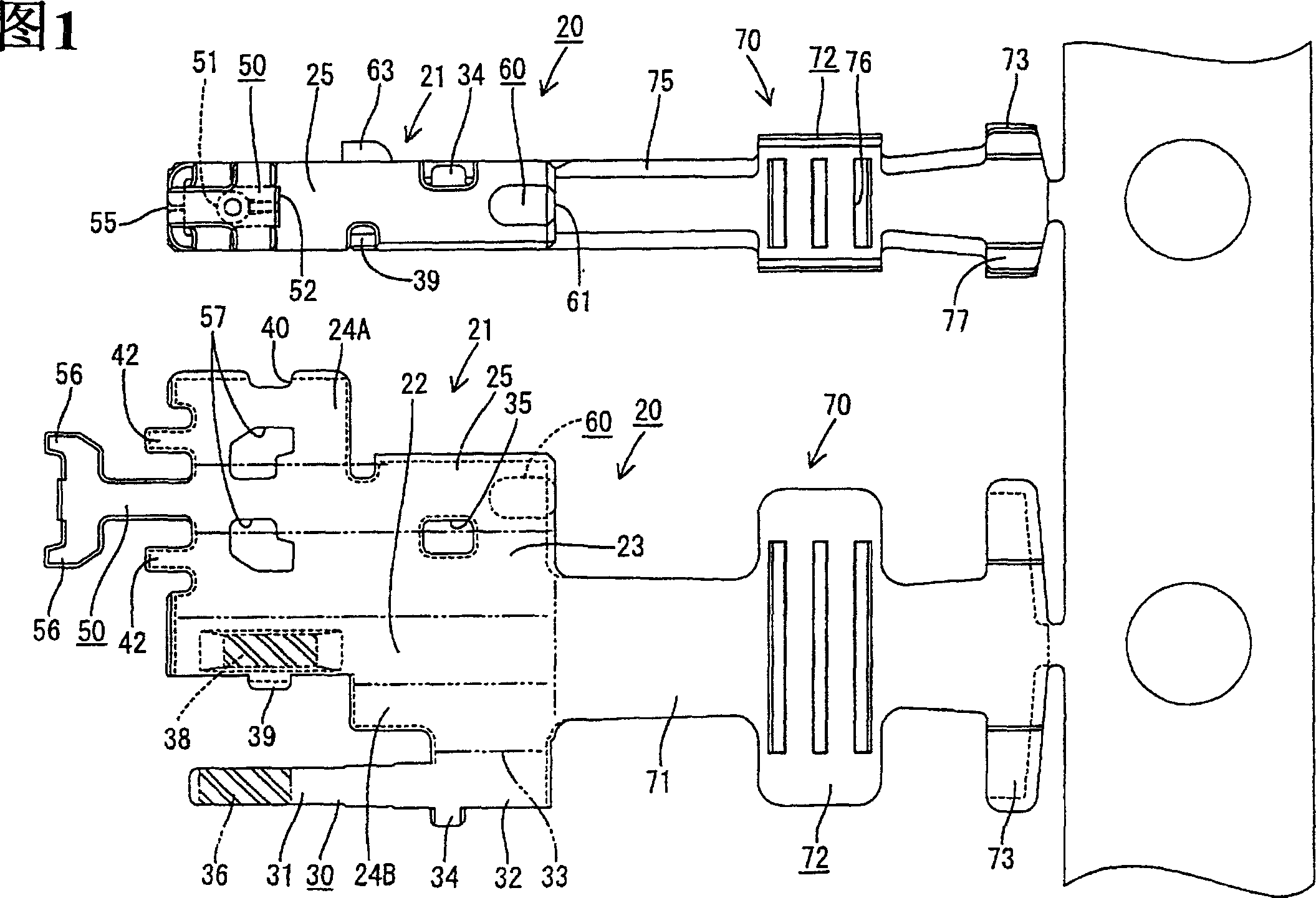
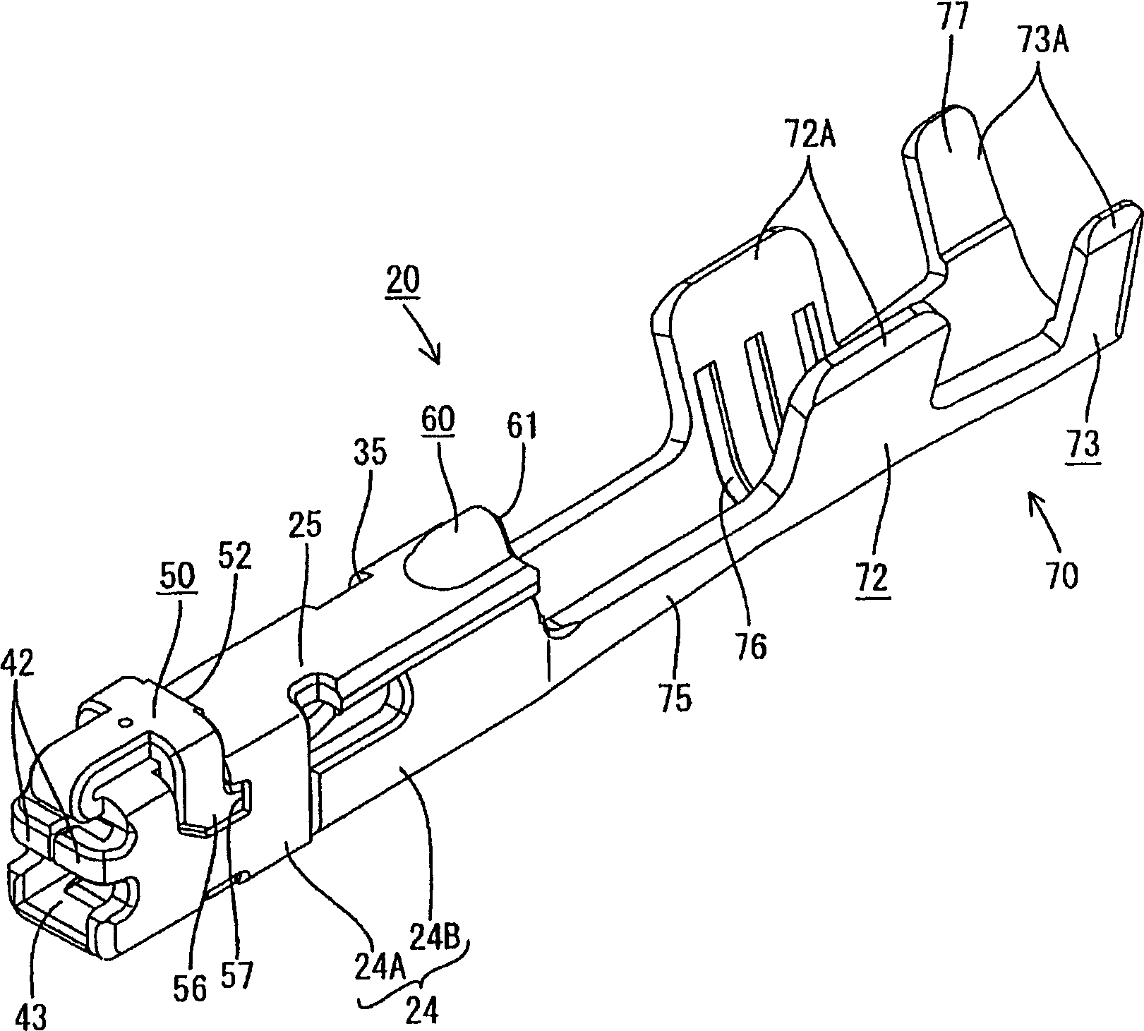
[0044] The female terminal fitting 20 of this embodiment is the upper side and figure 2 Assembled as shown in , preferably by stamping or cutting a conductive (preferably metal) sheet with good electrical conductivity into a formation as shown on the lower side of Figure 1, followed by multiple applications of bending, folding and / or pressing print. In general, the female terminal fitting 20 is such that a body portion 21, preferably substantially in the form of a rectangular tube, is provided before or adjacent to the wire connection portion 70 for fixing to the end of the wire 10, and a mating male terminal fitting Mt (see Figure 11 ) is at least partially inserted into the body portion 21 from the front.

[0045] The female terminal fitting 20 is or will be at least partially housed in the female housing 15 after being connected to the end of the insulated ...


PUM


Abstract

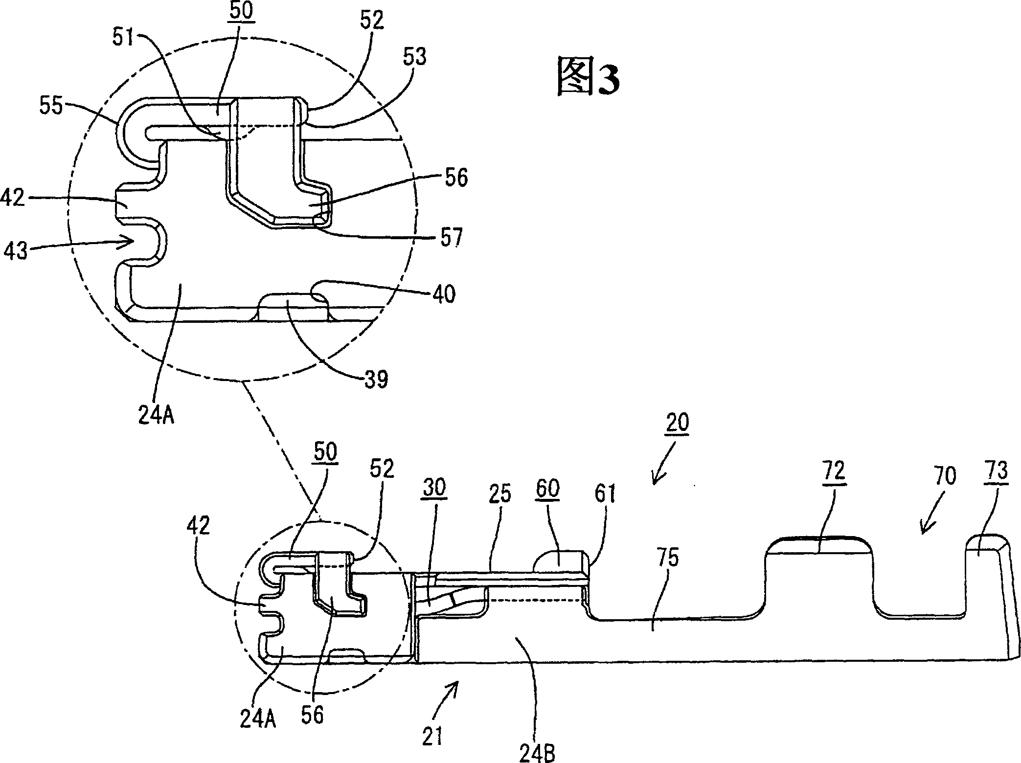
An object of the present invention is to reduce an inserting force while ensuring a sufficient locking force. A primary engaging portion 50 engageable with a locking portion 17 is formed by folding back a portion extending from the front edge of a ceiling plate 25 of a main portion 21. A folded portion 50 of the primary engaging portion 50 is rounded. Since a female terminal fitting 20 is inserted into a cavity while bringing the rounded folded portion 55 into contact with the locking portion 17, resistance is smaller and a smaller inserting force can be realized. Since the primary engaging portion 50 is distanced from the ceiling plate 25 by way of an embossed supporting portion 51, a larger area of engagement with the locking portion 17 can be provided. Since a slanted surface 53 is formed at a corner of a locking surface 52 closer to the ceiling plate 25, the leading end of the locking portion 17 acts to intrude at the inner side of the slanted surface 53, thereby securely preventing the locking portion 17 from escaping by sliding on the locking surface 52.

Description

technical field [0001] The present invention relates to a female terminal fitting and a connector equipped with the fitting. Background technique [0002] The structure of the female terminal joint is generally as follows: the elastic contact piece that is in contact with the mating male terminal joint is arranged in the main body part that is basically a rectangular tube, and is inserted into the cavity of the connector housing from the rear and passes through the cavity The formed resin locking portion is held there by engagement with the locking hole formed in the side plate of the main body portion. As the female terminal fitting is further miniaturized, the edge of the resin locking portion fitted into the main body portion is reduced, so that a sufficient locking force cannot be secured. In view of this, it has been proposed to form an engaging portion on the outer surface of the main body portion and engage a resin lock portion with the engaging portion. Such a conn...

Claims


Application Information

Patent Timeline
Patent Type & Authority Applications(China)
IPC IPC(8): H01R13/11H01R13/115H01R13/42H01R13/422H01R13/436H01R43/16
CPCH01R13/113H01R13/4223H01R13/4362H01R43/16
Inventor 田端正明儿岛映二
Owner SUMITOMO WIRING SYST LTD
Learn More