Method for screening magnetic field generated by electrical power transmission line and electrical power transmission line so screened
A technology for power transmission lines, cables, used in the installation of cables, cable installation in ground conduits, electrical components, etc.
- Summary
- Abstract
- Description
- Claims
- Application Information
AI Technical Summary
Problems solved by technology
Method used
Image
Examples
example 1
[0084] The applicant has measured the magnetic field generated above the ground by the buried power lines described above under several different operating conditions.
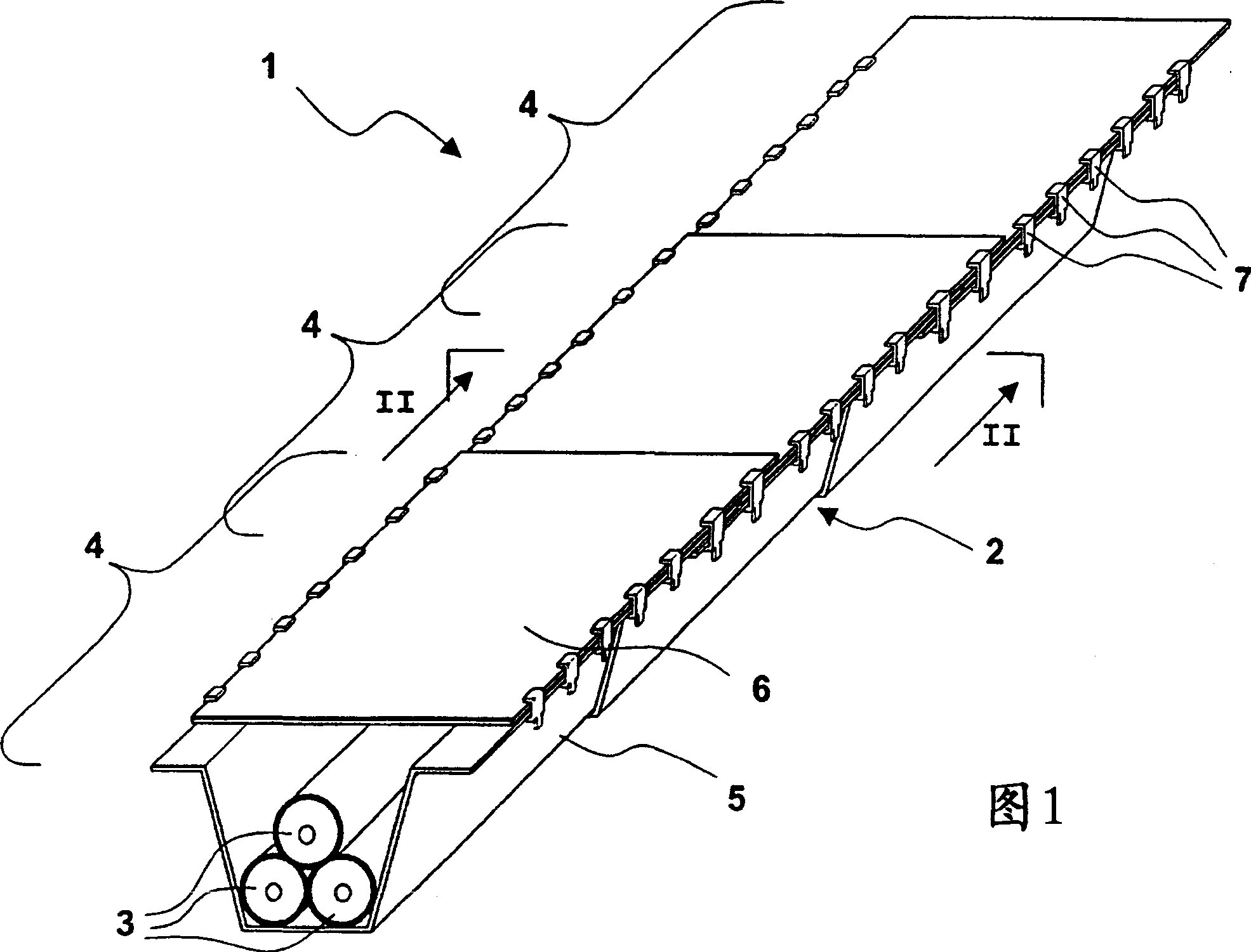
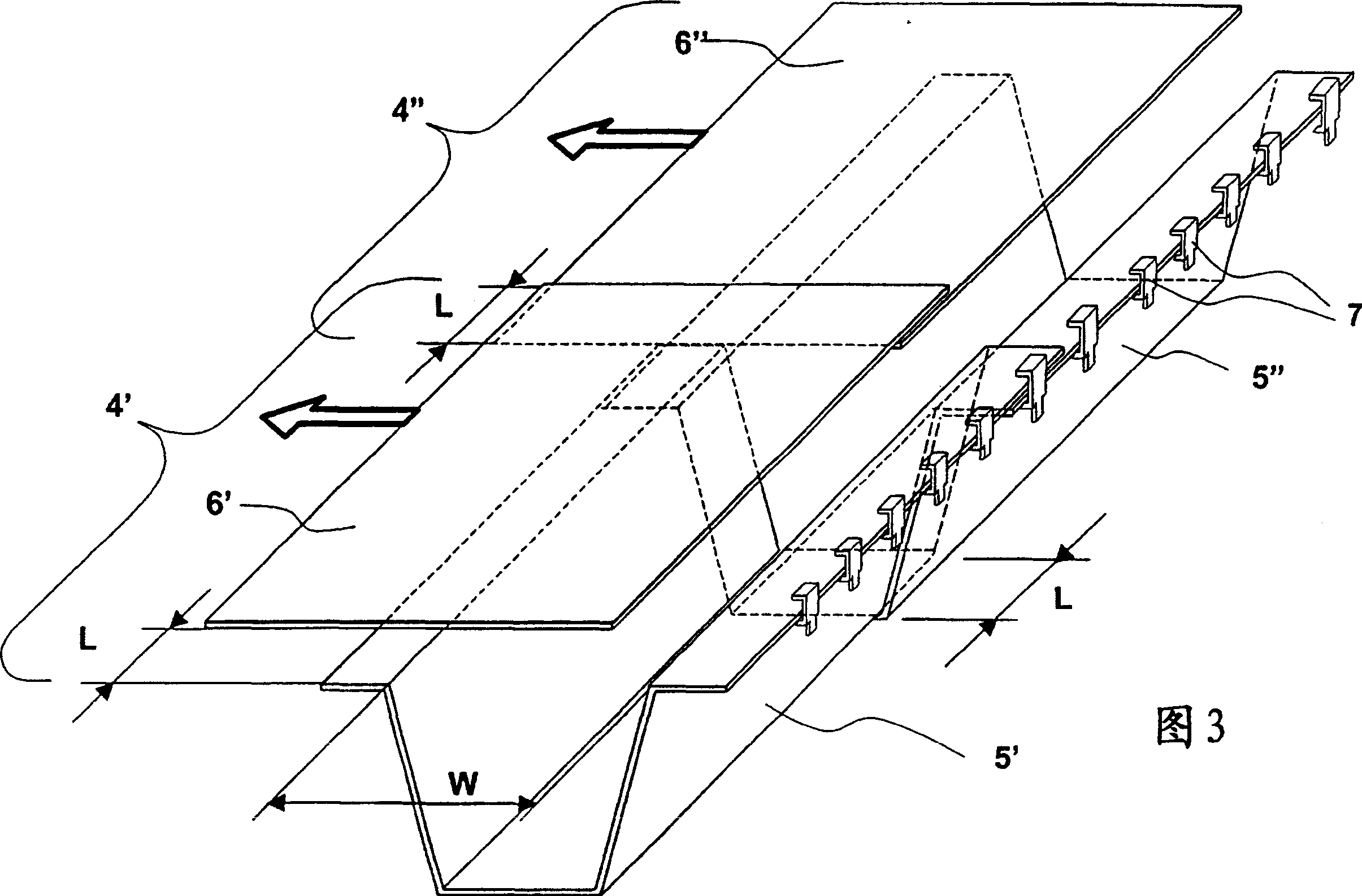
[0085] The test circuit consisted of a current generator, 3 cables 3 in trefoil configuration connected to said generator, a 50 meter long cylindrical steel pipe containing cables 3 from the outlet of said generator, and 6 longitudinal sections 4 of the cables at the ends of the cylindrical duct. At the outlets of the 6 sections 4 the cables 3 are short-circuited. The longitudinal sections 4 are overlapped by 200mm below ground and spaced 1.4 meters apart. A magnetometer model PLM-100WB Handheld ELF manufactured by MACINTYRE ELECTRONIC DESIGNASSOCIATES, INC. (485 Spring Park Place, Herndon, VA 20170) was used 1 meter above the ground between the third and fourth sections (i.e., in the middle of the transmission line ) to measure the magnetic field.
[0086] The dimensions of the bottom member 5 are as follo...
example 2
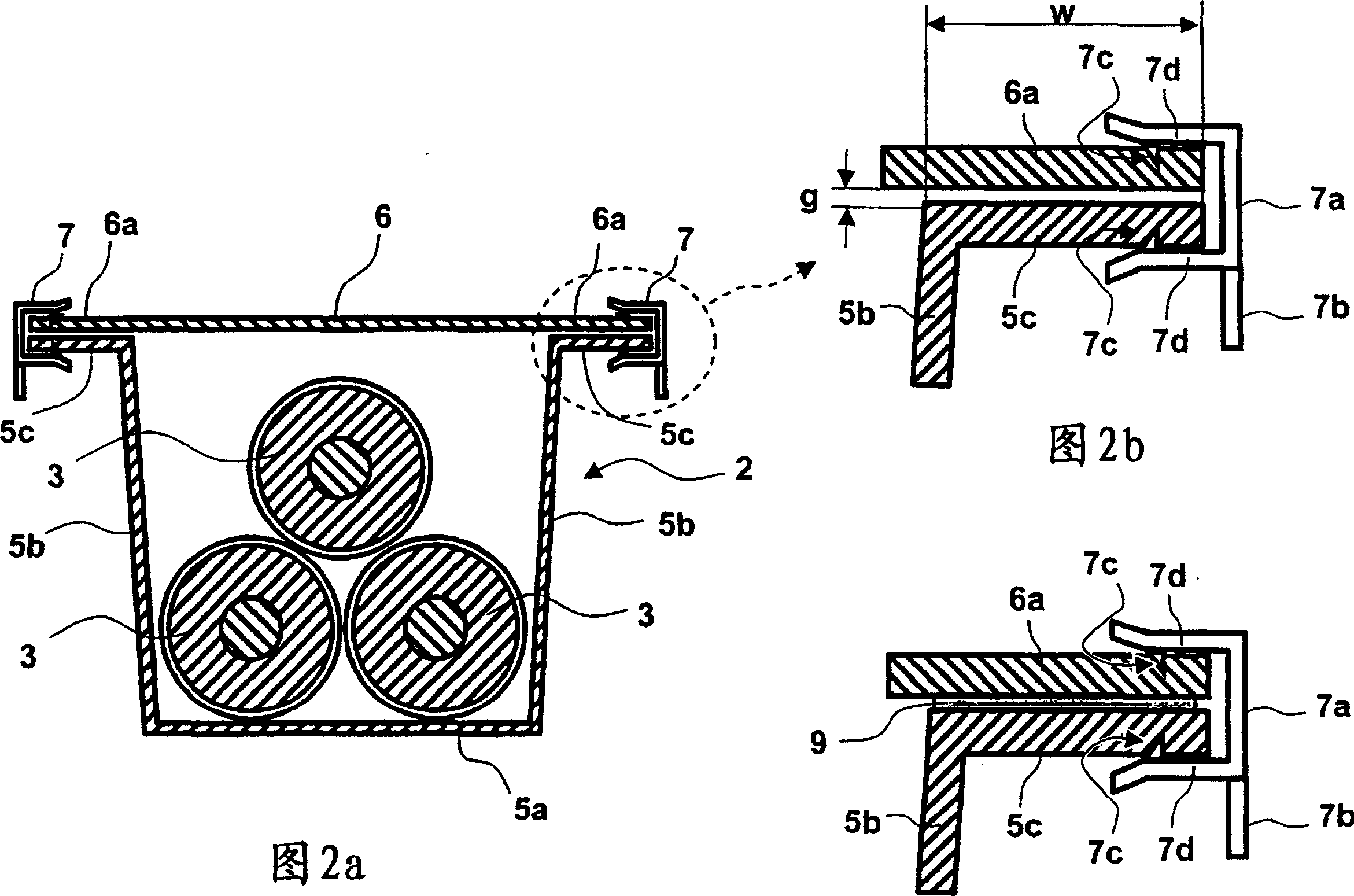
[0106] The applicant has also determined the change of the magnetic field 1 meter above the ground when the measurement position is changed along the transverse direction (ie the direction perpendicular to the pipeline). The shape, size and material of the pipe 2 are the same as in Example 1, and the following connection conditions are considered:
[0107] a) no connection between the bottom 5 and the cover 6, and a good insulation between them is obtained by means of inserting a nylon plate in between;
[0108] b) connected by clips 7 every 50cm;
[0109] c) connected by clips 7 every 25cm;
[0110] Image 6 represents the result of this experiment. It can be seen that the curve is bell-shaped and is maximum at the point of zero abscissa, that is, the maximum in the mid-plane of the pipe 2 . It can also be seen that the percentage improvement achievable by using the clip 7 is substantially constant by virtue of leaving the wire 1 .
example 3
[0112] The Applicant has also carried out a new set of measurements in order to compare the shielding effectiveness of different solutions by means of "ad hoc" parameters. This parameter, referred to herein as "electrical continuity", is denoted by the symbol λ:
[0113] λ = 100 B n - B i B n
[0114] where B n is the maximum magnetic field measured 1 meter above the ground between the bottom 5 and the cover 6 under the condition of complete electrical insulation by inserting a nylon plate (for example, using the same instrument as in Example 1), B i is the maximum magnetic field measured at 1 meter above the ground under specified operating conditions. The parameter λ is independent of the measurement distance, so it is an absolute indicator of the increase i...
PUM
 Abstract
Description
Claims
Application Information
 - R&D
- Intellectual Property
- Life Sciences
- Materials
- Tech Scout
- Unparalleled Data Quality
- Higher Quality Content
- 60% Fewer Hallucinations
Browse by: Latest US Patents, China's latest patents, Technical Efficacy Thesaurus, Application Domain, Technology Topic, Popular Technical Reports.
© 2025 PatSnap. All rights reserved.Legal|Privacy policy|Modern Slavery Act Transparency Statement|Sitemap|About US| Contact US: help@patsnap.com


