Switching circuit, switching method, protection apparatus and battery module

A switching circuit and switching device technology, which is applied to circuit devices, automatic disconnection emergency protection devices, emergency protection circuit devices, etc. safety effect

Inactive Publication Date: 2005-11-02
SONY CORP
View PDF9 Cites 5 Cited by
  • Summary
  • Abstract
  • Description
  • Claims
  • Application Information

AI Technical Summary

Problems solved by technology

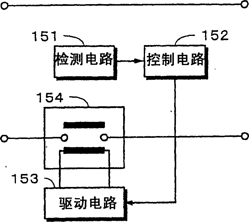
[0006] However, in such a circuit, when the detection circuit and the control circuit are damaged due to overcurrent, there is a high possibility that the electromagnetic switch will always be in the ON state.
[0007] In the past, it was impossible to confirm whether the electromagnetic switch 154 was in the cut-off state
Therefore, there is the following problem: When the electromagnetic switch 154 is damaged or the melting contact is welded, it cannot be disconnected.
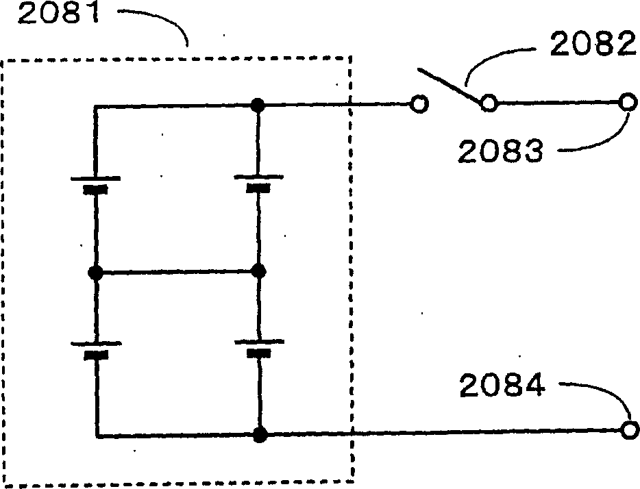
[0013] Here, the battery pack shown in FIG. 4 has the following problem: in the battery block 2088 to which a plurality of batteries are connected, if one battery is short-circuited, an overcurrent flows through the battery, and its safety cannot be ensured.

Method used


Image

  • Switching circuit, switching method, protection apparatus and battery module
  • Switching circuit, switching method, protection apparatus and battery module
  • Switching circuit, switching method, protection apparatus and battery module

Examples


Embodiment Construction

[0078] The basic structure of the present invention will be described below with reference to FIG. 5 . At least two drive coils L1 and L2 are provided in the electromagnetic switch 1 . The driving coil L1 turns off the switch SW1 by a current (overcurrent) flowing into the switch SW1 equal to or greater than a predetermined current value, and the driving coil L2 switches the direction of the current by the driving circuit 2 to turn on or off the switch SW1. The drive circuit 2 switches the direction of the current flowing through the drive coil L2 in response to a control signal supplied from the control circuit. Thus, the switch SW1 can be turned off by the overcurrent flowing through the drive coil L1.

[0079] A first embodiment in which the direction of the current flowing through the drive coil L2 is switched will be described with reference to FIG. 6 . As shown in FIG. 6 , the DC power supply E, the switches 11 and 12 connected in series, and the switches 13 and 14 con...


PUM


Abstract

PROBLEM TO BE SOLVED: To prevent the contact of a switch from sticking without arranging a detection circuit.SOLUTION: In an electromagnetic switch 1, at least two driving coils L1 and L2 are arranged. The driving coil L1 performs operation which turns a switch SW1 off by a current flowing in the switch SW1 e.g. excess current. The driving coil L2 is excited or demagnetized with a drive circuit 2 and performs operation which turns the switch SW1 on or off. The drive circuit 2 excites or demagnetizes the driving coil L2 according to a control signal supplied from a control circuit 3. As a result, the switch SW1 is turned off by current flowing in the driving coil L1.

Description

technical field [0001] The present invention relates to a switching circuit, a switching method, a protection device, and a battery pack for protecting electrical parts, such as lithium ion secondary batteries, from overcurrent. Background technique [0002] In the past, when detecting an overcurrent in a circuit, a detection circuit was used to detect the current in order to judge whether the detected current was an overcurrent. For example, as shown in FIG. 1 , a detection circuit 151 is used to detect the current. The detected current is supplied to the control circuit 152 . Whether or not the supplied current is an overcurrent is judged by the control circuit 152 , and the judgment result is supplied to the drive circuit 153 as a control signal. [0003] The electromagnetic switch 154 is energized or demagnetized by the drive circuit 153 in accordance with the supplied control signal. As an example, the excited electromagnetic switch 154 is in the off state, and the d...

Claims


Application Information

Patent Timeline
Patent Type & Authority Applications(China)
IPC IPC(8): H02H3/087H01H71/26H01M2/34
CPCY02E60/12Y02E60/10
Inventor 永井民次山崎和夫秋保均会田孝行榎本健司
Owner SONY CORP
Why Eureka
Try Eureka