Distributed arc electroerosion

一种电蚀、电弧的技术,应用在电弧焊设备、电路、电极制造等方向,能够解决增加叶盘成本、大时间和费用等问题

Active Publication Date: 2005-11-09
GENERAL ELECTRIC CO
View PDF2 Cites 30 Cited by
  • Summary
  • Abstract
  • Description
  • Claims
  • Application Information

AI Technical Summary

Problems solved by technology

[0022] Although there are various processes for processing materials in the production of gas turbine blisks, the manufacturing process still requires a lot of time and expense, which increases the cost of the blisks accordingly

Method used


Image

  • Distributed arc electroerosion
  • Distributed arc electroerosion
  • Distributed arc electroerosion

Examples


Embodiment Construction

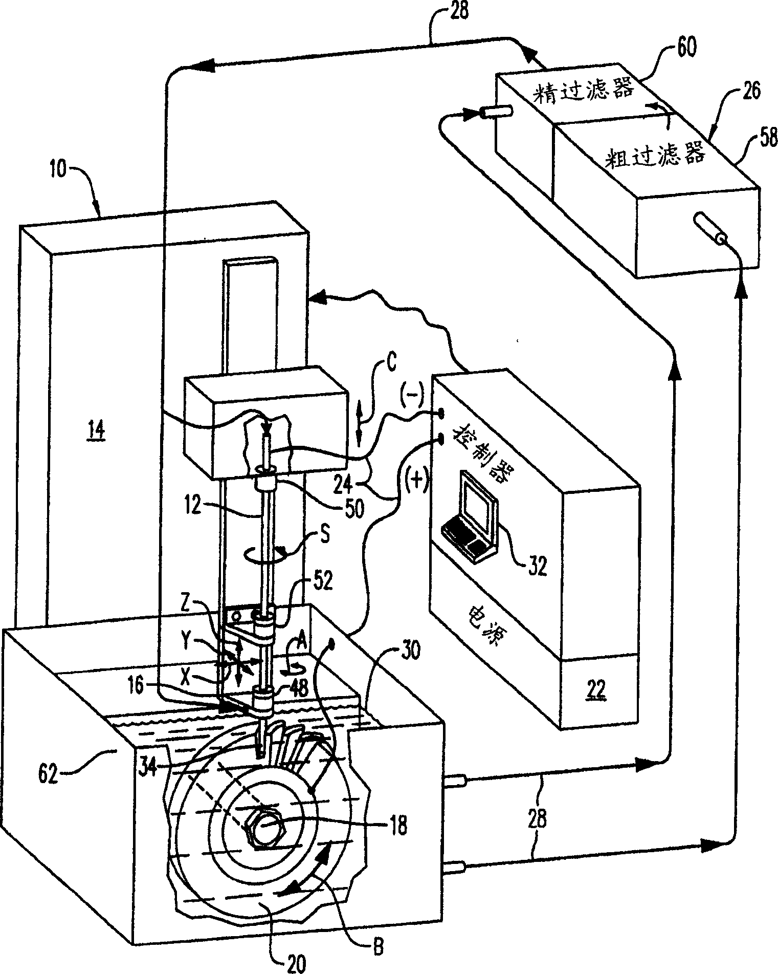
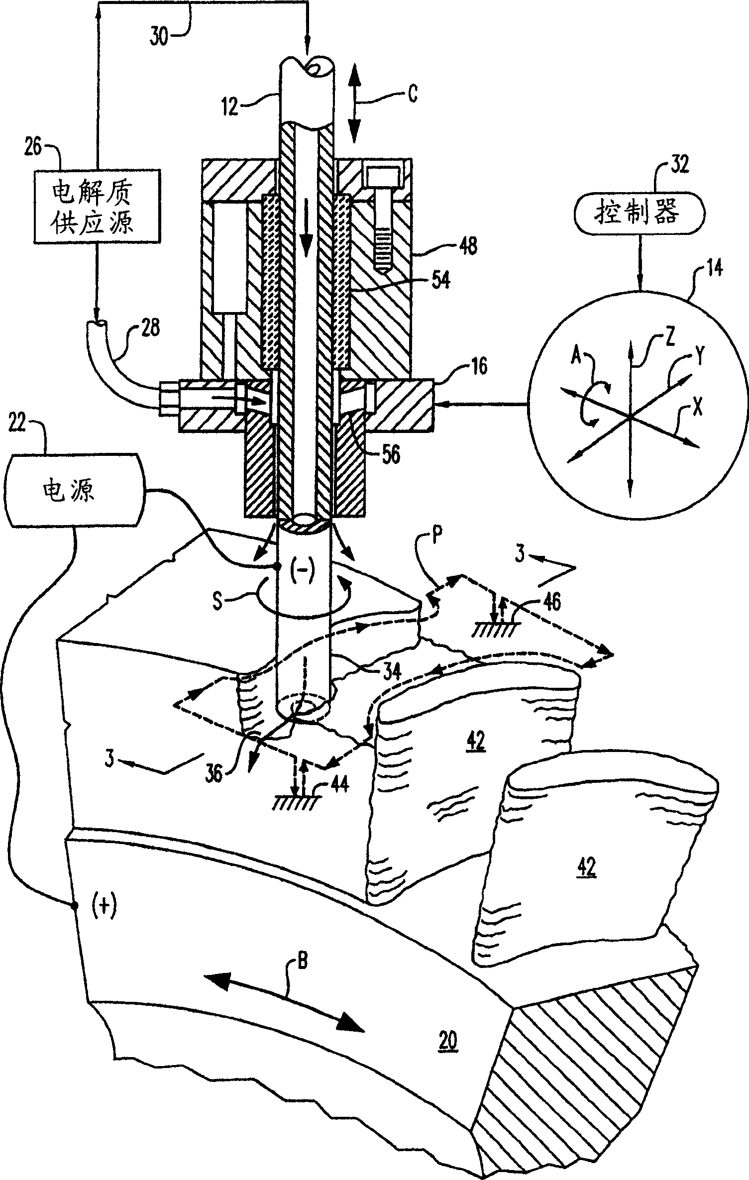
[0029] figure 1 An electroerosion machine or apparatus 10 comprising a tubular cutting tool or electrode 12 is schematically shown. The apparatus includes a multi-axis numerically controlled (NC) machine 14 including a tool holder 16 that supports the electrode for rotation or spinning S in operation and has multiple axes of movement. The machine also comprises a suitable support table in the typical form of a rotating mandrel 18 supporting the workpiece 20 and preferably having an additional axis of movement.

[0030] Means in the form of a conventional direct current (DC) power source 22 are provided to transmit electrical energy through the electrode 12 and workpiece 20 in operation. The power supply includes suitable electrical leads 24 respectively connected to the electrode 12, which in one embodiment acts as the cathode (-), and to the workpiece, which acts as the anode (+). In other alternative embodiments, the polarity may be reversed to anodic electrodes and cathod...


PUM


Abstract

An electroerosion apparatus (10) includes a tubular electrode (12) supported in a tool head (16) in a multiaxis machine (14). The machine (14) is configured for spinning the electrode (12) along multiple axes of movement relative to a workpiece (20) supported on a spindle having an additional axis of movement. A power supply (22) powers the electrode (12) as a cathode and the workpiece (20) as an anode. Electrolyte (30) is circulated through the tubular electrode (12) during operation. And, a controller (32) is configured to operate the machine (14) and power supply (22) for distributing multiple electrical arcs between the electrode (12) and workpiece (20) for electroerosion thereof as the spinning electrode travels along its feedpath.

Description

technical field [0001] The present invention relates generally to manufacturing processes, and more specifically, the present invention relates to machining. Background technique [0002] Precision machining is typically achieved using multi-axis numerically controlled (NC) milling machines. The cutting tool is suspended from a tool holder having generally three orthogonal translational axes and corresponding one or more additional rotational axes. The workpiece or component to be machined is fixedly mounted on a base that provides it with an additional axis of translational or rotational movement. [0003] In operation, a numerically controlled (NC) machine is programmed into software that controls the machining or cutting path of a tool to precisely remove material from a workpiece to its desired final dimensions. A typical milling machine includes a rotating cutting tool with a controlled feed path to remove material from a workpiece in successive operations until the d...

Claims


Application Information

Patent Timeline
Patent Type & Authority Applications(China)
IPC IPC(8): B23H1/00B23H1/02B23H7/26B23H7/32B23H9/10B23K9/013
CPCB23H9/10B23K9/013B23H1/022B23H2400/10B23H7/32B23H5/02
Inventor M·S·兰菲尔B·魏R·原J·F·维斯塞斯
Owner GENERAL ELECTRIC CO
Why Eureka
Try Eureka