Supercharge Your Innovation With Domain-Expert AI Agents!

Handle clip and folder comprising the same

A folder and handle technology, applied in folders, printing, binding, etc., can solve problems such as inability to use, unsmooth use, inconvenience, etc.

Inactive Publication Date: 2005-11-23
LECO STATIONERY MFG CO LTD
View PDF0 Cites 4 Cited by
  • Summary
  • Abstract
  • Description
  • Claims
  • Application Information

AI Technical Summary

Problems solved by technology

like figure 2 As shown, when the handle 5 is rotated along the first direction, the handle side wall 13 is likely to contact and collide with the base side wall 7, resulting in unsmooth and inconvenient use, and even the handle side wall 13 as shown in FIG. When inserted into the outside of the side wall 7 of the base, it is stuck and cannot be used

Method used


Image

  • Handle clip and folder comprising the same
  • Handle clip and folder comprising the same
  • Handle clip and folder comprising the same

Examples


Embodiment Construction

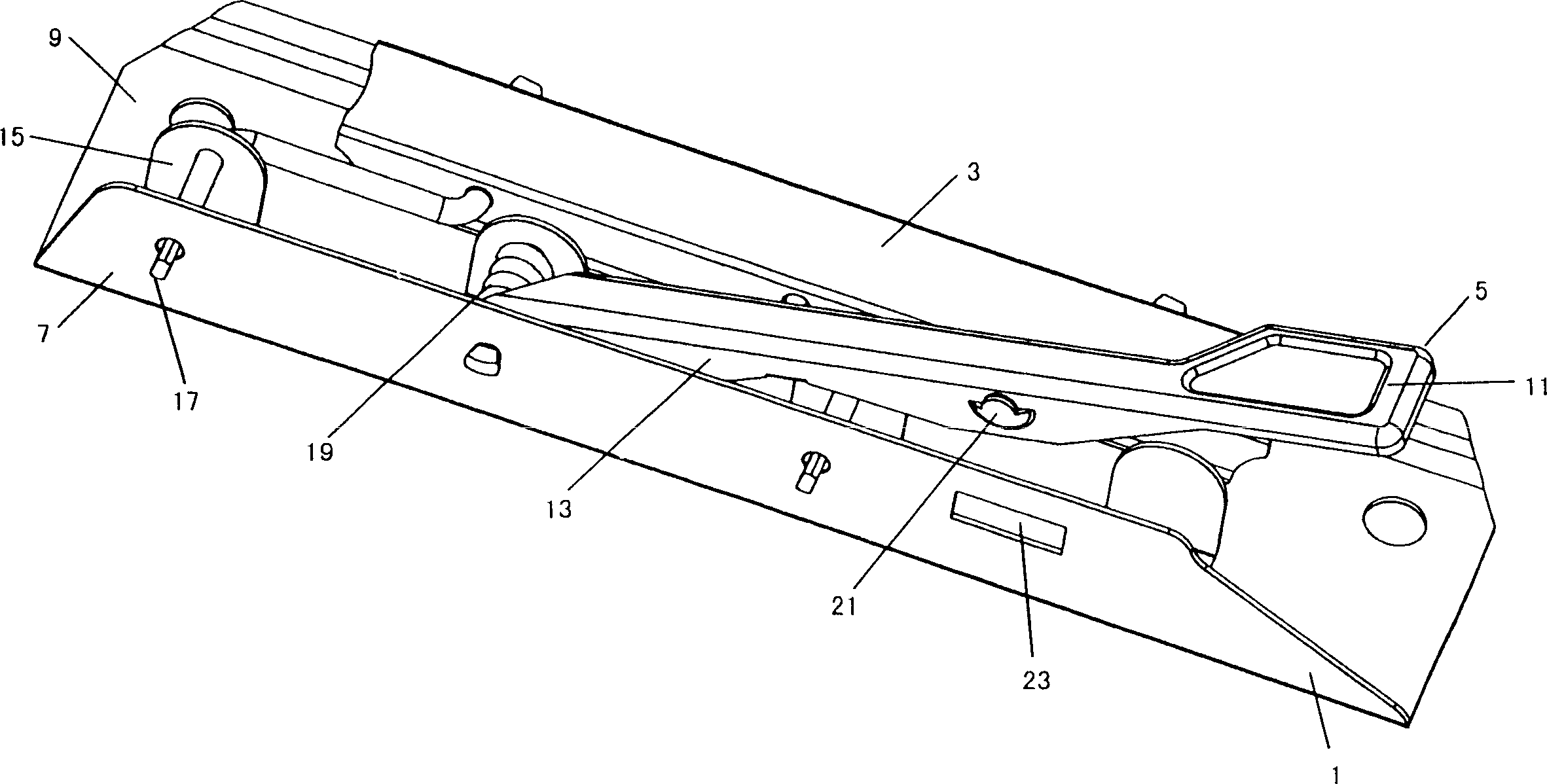
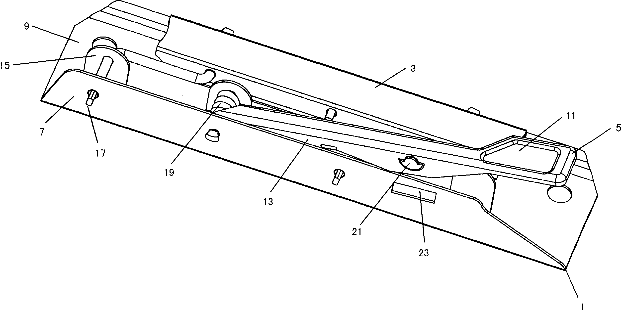
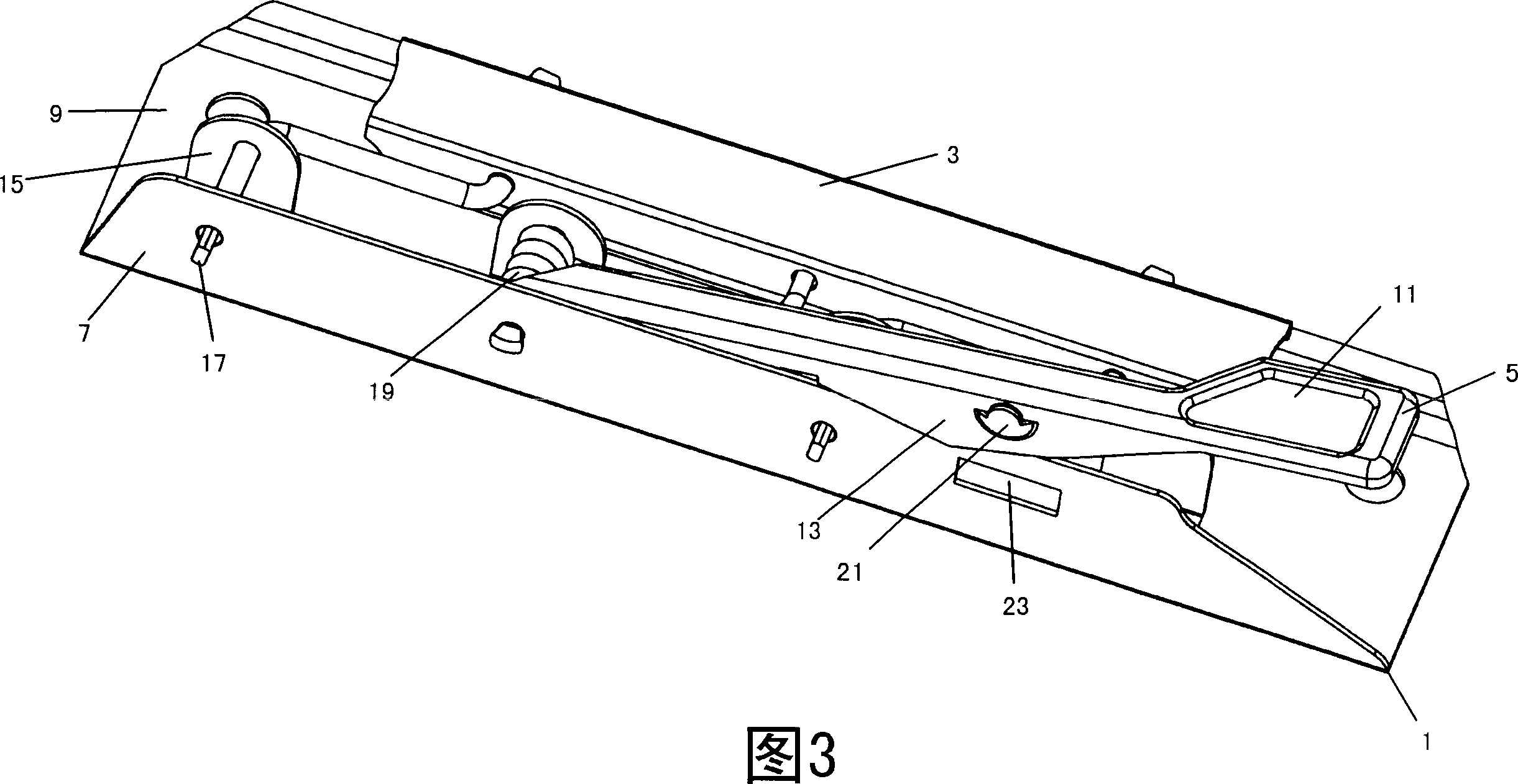
[0024] Such as Figure 4 - As shown in 6 and 11 , the handle clip according to the present invention generally includes a base 1 , a pressing part 3 and a handle 5 . The base 1 is bent at about 90 degrees to form upward standing side walls 7 and a horizontal bottom wall 9 . The pressing part 3 extends in a strip shape. The handle 5 includes a horizontal top wall 11 and a side wall 13 bent downward at about 90 degrees.

[0025] Four protruding walls 15 bent upward at approximately 90 degrees are formed on the bottom wall 9 of the base by stamping, and the number of protruding walls 15 can be more than four or less than four as required. The base 1, pressing part 3 and handle 5 are movably assembled together by means of three pivot shafts 17 and springs 19 supported by holes on the side walls of the base and the protrusion wall 15, so that the handle 5 can be wound around the support spring 19 The pivot shaft 17 is rotatably mounted on the inside of the side wall 7 of the bas...


PUM


Abstract

This invention provides a handgrip nip, which comprises base (1), pressing section (3) and handgrip (5), wherein the base (1) comprises the upright side wall (7) and horizontal floor (9), the handgrip (5) comprises the horizontal roof (11) and the bending side wall (13) with a projection part (21); in the base side wall (7) is arranged a hole corresponding to the projection part; the base, pressing section and handgrip can assembled movably together, which makes the handgrip rotating with the pivotal axis (17) which is used for supporting spring and fixed in the inner wall of the base, besides, the handgrip nip forms the guiding part in the handgrip side wall to guide the side wall. The invention also provides a file binder fixed with such handgrip nip.

Description

technical field [0001] The invention relates to a handle clip and a folder including the handle clip. Background technique [0002] A handle clip is a stationery widely used to store paper sheets and the like. figure 1 -3 shows a prior art handle clip. The existing handle clip usually includes a base 1 , a pressing part 3 and a handle 5 . The base 1 is bent at about 90 degrees to form upward standing side walls 7 and a horizontal bottom wall 9 . The pressing part 3 extends in a strip shape. The handle 5 includes a horizontal top wall 11 and a side wall 13 bent downward at about 90 degrees. Several protruding walls 15 are formed on the bottom wall 9 of the base part and are bent upward at about 90 degrees. By means of several pivot shafts 17 and springs 19 supported by the side walls of the base and the protruding wall 15, the base 1, the pressing part 3 and the handle 5 are movably assembled together so that the handle 5 can rotate around the pivot shafts of the support...

Claims


Application Information

Patent Timeline
Patent Type & Authority Applications(China)
IPC IPC(8): B42F1/00
Inventor 杜振源
Owner LECO STATIONERY MFG CO LTD
Features
  • R&D
  • Intellectual Property
  • Life Sciences
  • Materials
  • Tech Scout
  • Unparalleled Data Quality
  • Higher Quality Content
  • 60% Fewer Hallucinations
Learn More