
Electric connector

A technology of electrical connectors and electrical connections, applied in connection, fixed connection, circuits, etc., can solve problems such as high generation, accumulated heat, and abnormal operation of the central processing unit 21, so as to improve performance and facilitate heat dissipation

Inactive Publication Date: 2005-11-23
ADVANCED CONNECTION TECH
View PDF0 Cites 5 Cited by
  • Summary
  • Abstract
  • Description
  • Claims
  • Application Information

AI Technical Summary

Problems solved by technology

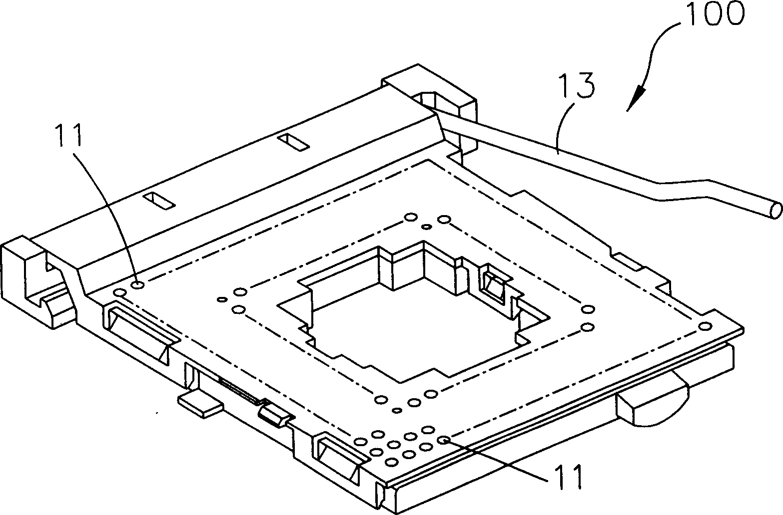
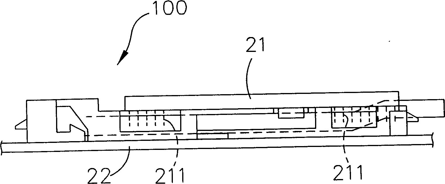
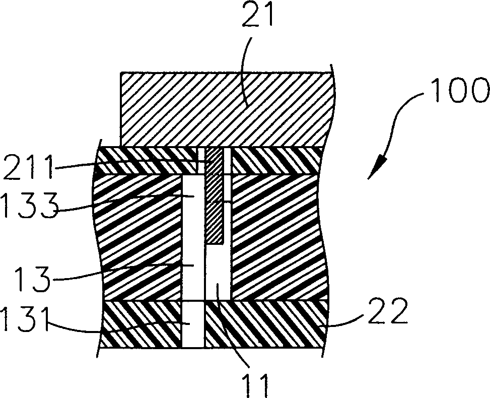
[0004] However, the connection between the pins 211 and the lead ends 133 is located in the through hole 11. Due to the rapid transmission of electronic signals during use, the central processing unit 21 generates heat, especially the connection between each pin 211 and each lead end 133. The temperature is the highest, because the electronic signal needs higher energy here, and the higher energy will generate higher heat, and because the heat generated here is limited in the through hole 11, the heat can only be transmitted by the electrical connector 100. The plastic shell itself or the terminal 13 itself is passed out slowly, so even if a powerful fan (not shown) is set up above the central processing unit 21 to assist heat dissipation, the air cannot be directly blown to the pin 211 and the lead terminal. 133 connection, so if the processing speed of the central processing unit 21 is to be further improved, the problem of accumulating heat at the connection between the pin 211 and the lead terminal 133 must be solved, otherwise the central processing unit will be damaged due to too much heat and too high a temperature. 21 not functioning properly

Method used


Image

  • Electric connector
  • Electric connector
  • Electric connector

Examples


Embodiment Construction

[0022] 4 and 5 are preferred embodiments of the electrical connector of the present invention. The electrical connector 500 of this embodiment includes a base 6 , a plurality of terminals 7 and a protective body 8 .

[0023] The base 6 is a rectangular body, and has a mounting surface 601 and an opposite clamping surface 603. Two upright walls 611 extend vertically from opposite sides of the clamping surface 603. The two upright walls 611 are parallel to each other and Extend in a direction away from the mounting surface 601, and then vertically extend a transverse wall 612 towards each other inwardly. In this embodiment, the two transverse walls 612 are not in contact with each other and are parallel to the clamping surface 603. By The two upright walls 611 and the two transverse walls 612 form an accommodating space 605 on the clamping surface 603 .

[0024] A plurality of first through-holes 606 are penetrated on the base 6, and a second through-hole 607 is respectively pen...


PUM


Abstract

This invention provides one connector located on one circuit board and provides one transistor set to connect the transistor with circuit board, wherein, the connector comprises one base socket, several terminals and one protector; the socket has one fixing surface and one container space; the protector body is the movable containing space; the terminal has one first and second connectors relative to the socket to expose the second connector to the fixing surface and connected to the circuit board; the first connector is located in the containing space protected by the protector to move the protector when the transistor set is located in the containing space to make the terminal near to the first connector to dissipate the heat.

Description

technical field [0001] The invention relates to an electrical connector, in particular to an electrical connector which facilitates heat dissipation and improves performance. Background technique [0002] Such as figure 1 , 2 , 3, is a kind of existing zero insertion force electrical connector (ZIF) 100, and it is used for inserting for a central processing unit (CPU) 21, has a plurality of through-holes 11 on this electrical connector 100, each Each of the through holes 11 is provided with a terminal 13 , and the structure of the electrical connector 100 is a common technology, so it will not be described in detail. [0003] Each terminal 13 body is fixed in the through hole 11, and has a welding end 131 exposed on the bottom surface of the electrical connector 100, and an opposite lead end 133, the weld end 131 is welded on a circuit board 22, and the lead The terminal 133 is hidden in the through hole 11, and is used to electrically connect with the pin 211 below the c...

Claims


Application Information

Patent Timeline
IPC IPC(8): H01R12/51
Inventor 王敬順
Owner ADVANCED CONNECTION TECH
Learn More