Rotary jet engine

A technology of rotary jet and engine, which is applied in the direction of machines/engines, gas turbine devices, mechanical equipment, etc. It can solve the problems of complex structure of turbine and compressor, limitation of engine power and efficiency, easy to be burned by high-temperature gas, etc., and achieve weight reduction , Improve the initial temperature of gas, low cost and technical difficulty

Inactive Publication Date: 2007-03-07
李志文
View PDF0 Cites 4 Cited by
  • Summary
  • Abstract
  • Description
  • Claims
  • Application Information

AI Technical Summary

Problems solved by technology

[0002] The traditional turbojet engine is driven by the turbine through the rotating shaft to drive the compressor to rotate to achieve cyclical work. The rotating shaft must bear huge torque, which makes the rotating shaft easy to break; the turbine blades are easily burned by high-temperature gas due to difficulty in heat dissipation, which limit

Method used


Image

  • Rotary jet engine
  • Rotary jet engine
  • Rotary jet engine

Examples


Example Embodiment

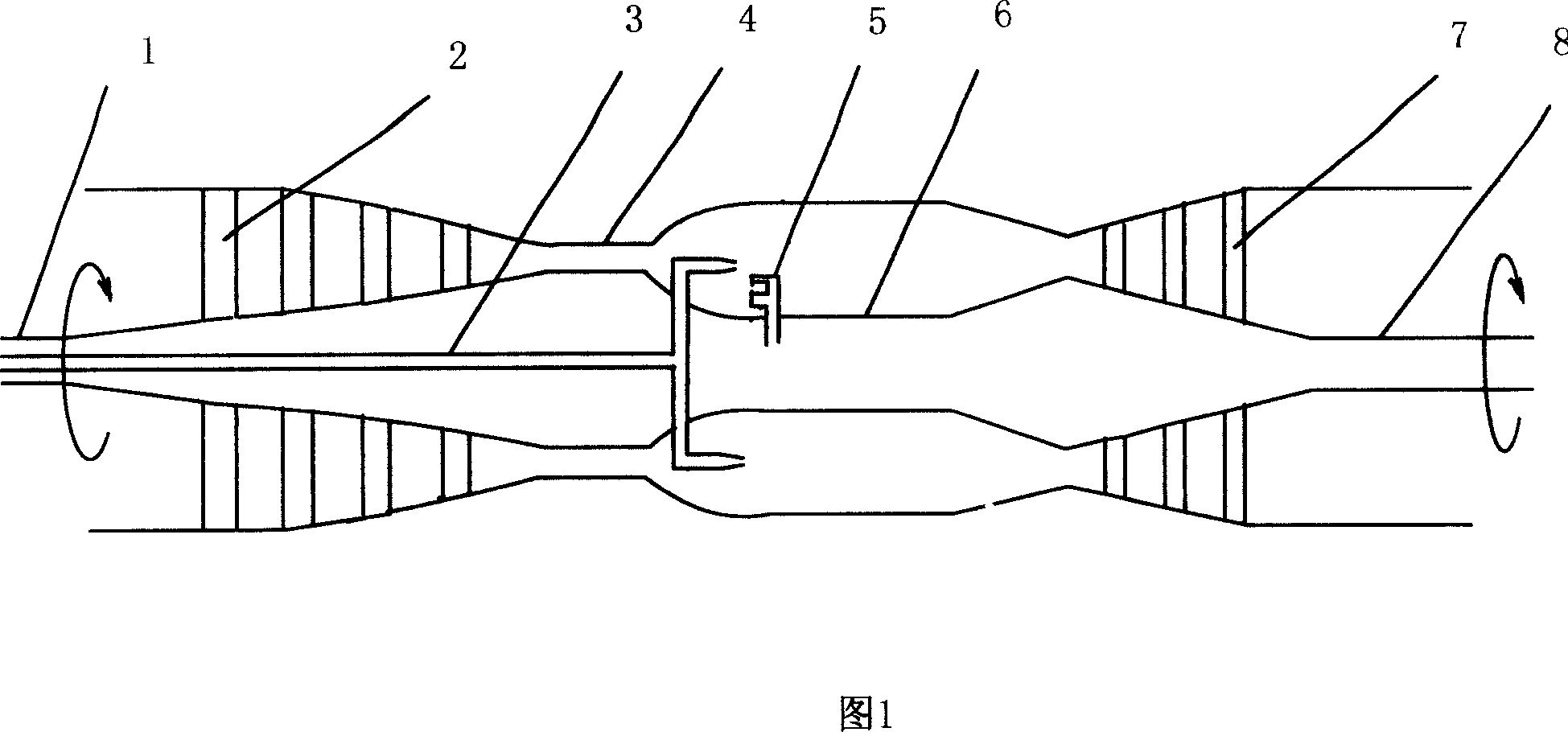
[0011] The present invention is different from the traditional turbojet engine. In the traditional turbojet engine, the turbine drives the compressor to rotate through the rotating shaft to realize the working cycle. The other parts of the engine are stationary, while the present invention consists of the blades (7) behind the combustion chamber. The inner wall (6) and the outer wall (4) drive the blades (2) to rotate around the axis, that is, the entire engine rotates to achieve a working cycle. The entire engine is a rotor, that is to say, the blades (2) and blades ( The two ends of 7) are respectively connected with the inner wall (6) and the outer wall (4), and the inner wall (6) is formed by connecting the inner wall of the compressor, the inner wall of the combustion chamber and the inner wall of the nozzle, and the outer wall (4) is made of the compressor The outer wall, the outer wall of the combustion chamber and the outer wall of the nozzle are connected; the left end (c...


PUM


Abstract

This invention relates to rotation spray motor, wherein, the blade and its two ends are connected to inner and outer walls; the inner wall left end is connected to rotation axis and right to rotation axis; motor left end axis has fuel tube connection; the fuel tube and spray mouth are connected; it is characterized by connecting two ends of blade to inner and outer walls for rotary operating.

Description

Technical field: [0001] The present invention relates to a jet engine, and more particularly to a rotary jet engine. Background technique: [0002] The traditional turbojet engine is driven by the turbine through the rotating shaft to drive the compressor to rotate to achieve cyclical work. The rotating shaft must bear huge torque, which makes the rotating shaft easy to break; the turbine blades are easily burned by high-temperature gas due to difficulty in heat dissipation, which limits the combustion chamber. The improvement of the initial temperature of the gas (the temperature before the turbine) limits the improvement of the power and efficiency of the engine; and the structure of the turbine and the compressor of the traditional turbojet engine is complex and the manufacturing cost is high and the weight is also relatively large. Invention content: [0003] The invention provides a rotary jet engine capable of improving or overcoming the disadvantages described in th...

Claims


Application Information

Patent Timeline
IPC IPC(8): F02C3/00
Inventor 李志文
Owner 李志文
Why Eureka
Try Eureka