Recording head, carriage and image forming apparatus

A technology of recording head and carrier, which is applied in printing and other directions, and can solve the problems of complex structure of inkjet head, complicated production process, and failure to absorb pressure changes in common ink chambers, etc.

Inactive Publication Date: 2005-11-23
RICOH KK
View PDF6 Cites 2 Cited by
  • Summary
  • Abstract
  • Description
  • Claims
  • Application Information

AI Technical Summary

Problems solved by technology

[0014] However, since buffer chambers are provided for individual ink chambers of ink jet recording heads according to Japanese Laid-Open Patent Application No. 6-191030, it is difficult to sufficiently reduce the rigidity of the buffer chambers.
Also, the structure of the inkjet head becomes complicated, thereby requiring a complicated production process to produce the inkjet recording head
Recently, the trend is to increase the number of nozzles of the inkjet recording head to meet the demand for high recording, but the str

Method used


Image

  • Recording head, carriage and image forming apparatus
  • Recording head, carriage and image forming apparatus
  • Recording head, carriage and image forming apparatus

Examples


Embodiment approach

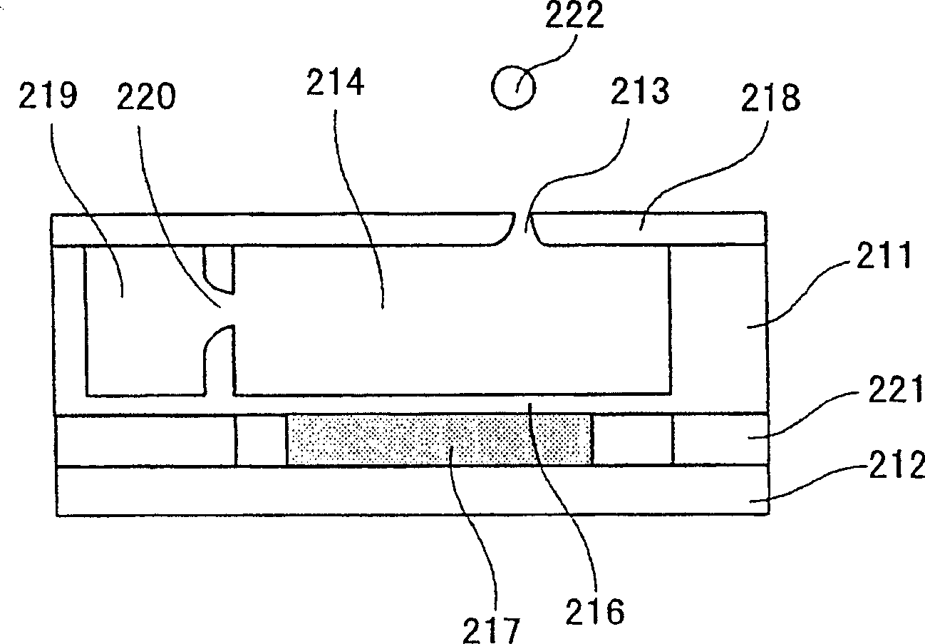
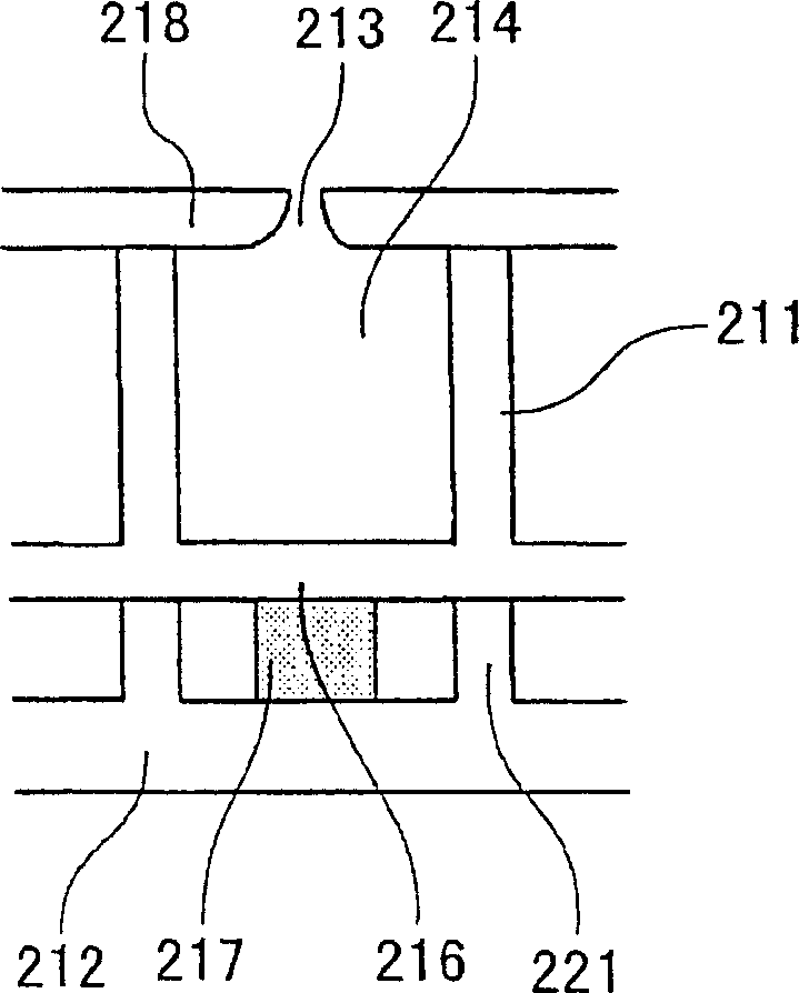
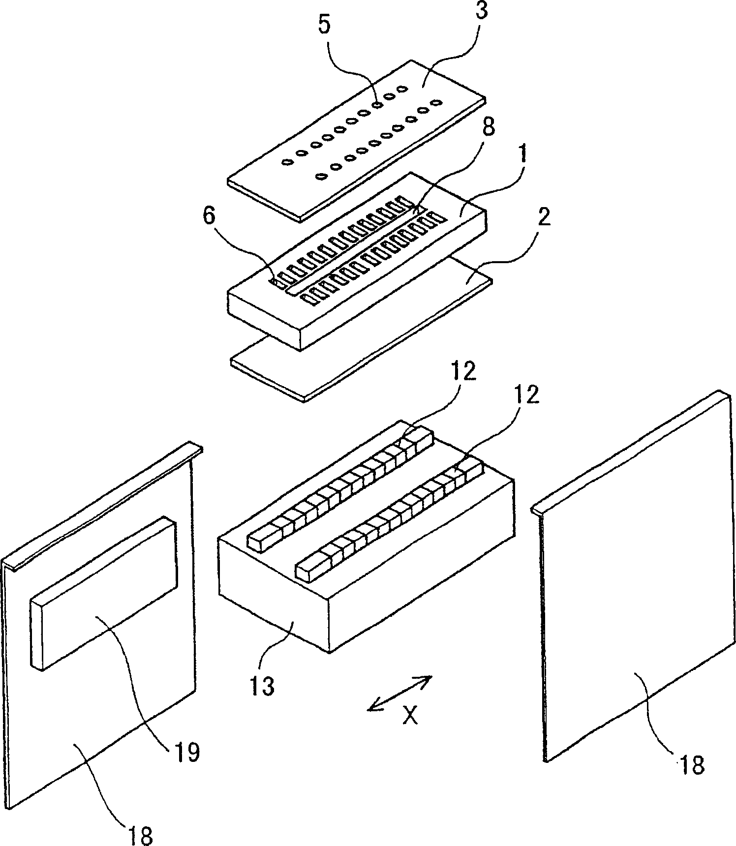
[0071] First, refer to Figures 3 to 5 A description is given of the first embodiment of the recording head according to the present invention. image 3 is an exploded perspective view showing this first embodiment of the recording head, and Figure 4 is a sectional view showing this first embodiment of the inkjet head taken along the longitudinal direction of the pressurized ink chamber (ie, along the direction perpendicular to the direction in which the nozzles are arranged). Figure 5 is the direction along which the nozzles are arranged ( Figure 4 A reverse cross-sectional view of this first embodiment of the recording head taken in A-A). According to this first embodiment of the recording head, the present invention is applied to an ink jet recording head.

[0072] Figures 3 to 5 The inkjet recording head shown in includes: a flow channel constituting substrate (ink chamber substrate) 1 made of single crystal silicon (Si), a vibrating plate 2 provided on the lower s...

no. 1 approach

[0160] Figure 18 and 19 The image forming apparatus shown in , that is, an inkjet recording apparatus, accommodates a printing mechanism 112 in a main body 111 . This printing mechanism 112 includes: a carriage 123 movable in the main scanning direction inside the main body 111; structure of the inkjet recording head 124, an ink cartridge 125 for supplying ink to the inkjet recording head, and the like. Figure 19 A paper feed cassette (or paper feed tray) 114 shown in is detachably provided at the lower part of the main body 111, and a stack of a plurality of recording media (in this case, recording paper) 113 is housed in the paper feed cassette 114. . The recording medium 113 can be loaded onto the paper feed cassette 114 from the front of the inkjet recording apparatus. The manual feed tray 115 for manually supplying the recording medium 113 can be used as Figure 19 Closes as shown and opens counterclockwise when in use. The printing mechanism 112 prints an image o...


PUM

PropertyMeasurementUnit
Young's modulusaaaaaaaaaa

Abstract

A recording head is provided with a plurality of nozzles for ejecting a fluid, a plurality of pressure-applied chambers arranged in a predetermined direction and each communicating with a corresponding one of the nozzles, and a common chamber having a plurality of wall surfaces and configured to supply the fluid to the pressure-applied chambers. At least one of the wall surfaces of the common chamber, along the predetermined direction, has a pressure absorbing surface with a rigidity lower than those of other wall surfaces and configured to absorb a pressure change, and the pressure absorbing surface is formed by a pressure absorbing member having a non-uniform thickness.

Description

technical field [0001] The present invention relates generally to recording heads, carriages and image forming apparatuses, and more particularly to recording heads for ejecting fluids such as ink, carriages having at least one recording head, and imaging apparatuses having at least one carriage . [0002] The inkjet recording device can be used as an image forming device for a printer, a facsimile device, a copying device, a plotter, and the like. The inkjet recording apparatus is equipped with an inkjet recording head including an ink flow channel and a pressure switching device for applying pressure to the ink by changing the pressure in the ink flow channel. The ink flow channels are also commonly referred to as ejection chambers, pressure chambers, pressurized ink chambers, ink chambers, and the like. Background technique [0003] There is a known ink jet recording head which uses an electromechanical transducing element such as a piezoelectric element as a pressure t...

Claims


Application Information

Patent Timeline
IPC IPC(8): B41J2/045B41J2/055
CPCB41J2002/14419
Inventor 尾方贤一吉田崇裕江口裕俊
Owner RICOH KK
Why Eureka
Try Eureka