Method, device and terminal for reducing transmission delay by eyeball prediction

A transmission delay, eyeball technology, applied in transmission systems, optics, instruments, etc., can solve the problems of unpredicted eyeball position, low resolution, transmission time delay, etc., to improve continuous capture and recording of eyeball position, save transmission bandwidth, The effect of reducing transmission delay

Inactive Publication Date: 2019-01-15
孙建军
View PDF0 Cites 1 Cited by
  • Summary
  • Abstract
  • Description
  • Claims
  • Application Information

AI Technical Summary

Problems solved by technology

[0002] The retinal resolution of the human eye is not uniform, only the macular area has high resolution, and the rest of the area has low resolution. However, the entire field of view of wearable (VR) displays has the highest resolution, which has a great impact on computing performance and transmission channels. necessary pressure
The current method does not predict the position of the eyeball, and cannot predict the picture information that the user sees in advance, which brings delay to the transmission time and the transmission rate is very low

Method used


Image

  • Method, device and terminal for reducing transmission delay by eyeball prediction
  • Method, device and terminal for reducing transmission delay by eyeball prediction
  • Method, device and terminal for reducing transmission delay by eyeball prediction

Examples


Embodiment Construction

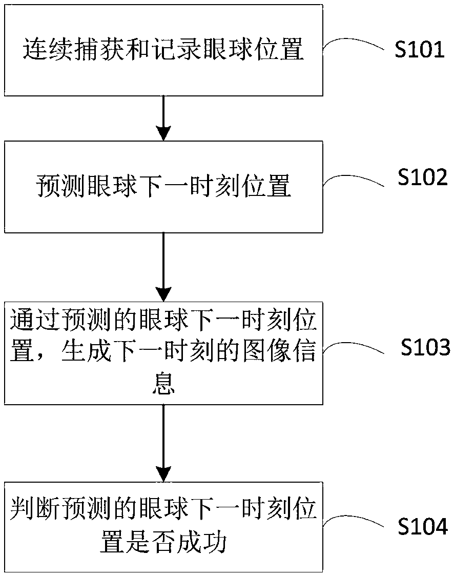
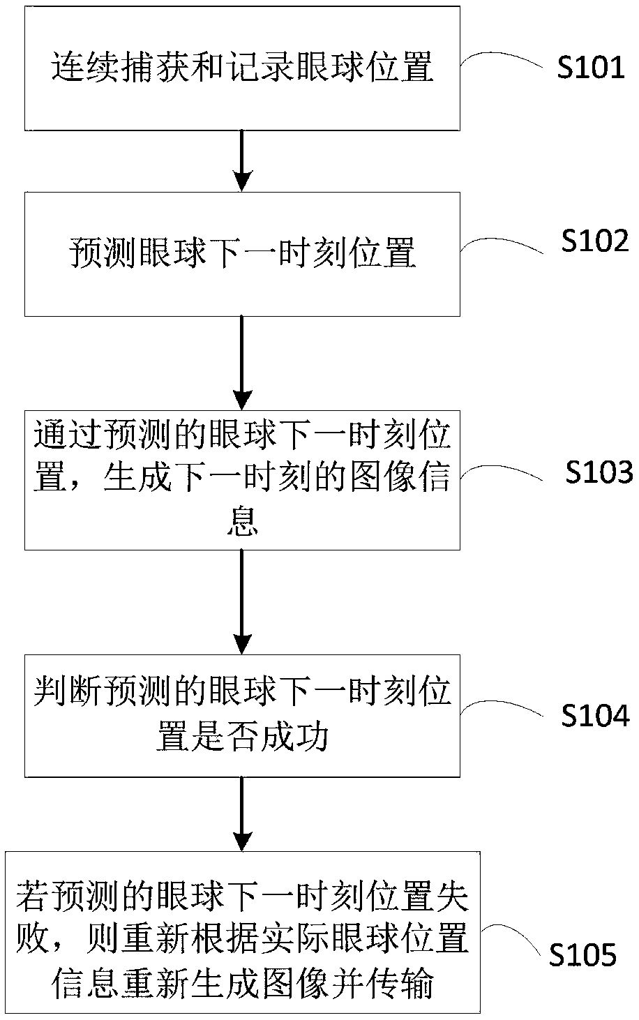
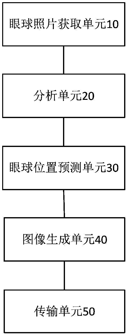
[0036] The specific embodiments of the present invention will be further described in detail below in conjunction with the accompanying drawings.

[0037] The following description and drawings fully illustrate specific embodiments of the present invention to enable those skilled in the art to practice them. Other implementations may include structural, logical, electrical, process, and other changes. The examples only represent possible changes. Unless explicitly required, the individual components and functions are optional, and the order of operations may vary. Parts and features of some embodiments may be included in or substituted for parts and features of other embodiments. The scope of the embodiments of the present invention includes the entire scope of the claims, and all available equivalents of the claims. In this context, these embodiments of the present invention may be individually or collectively denoted by the term "invention", this is only for convenience, and...


PUM


Abstract

The invention relates to a method, a device and a terminal for reducing transmission delay by an eyeball prediction. The method comprises the following steps of: a, continuously capturing and recording the position of the eyeball; b, predicting the position of the eyeball at the next moment; c, generating an image information of the next moment by the predicted position of the eyeball at the nextmoment; d, judging whether the predicted position of the eyeball at the next moment is successful; e, regenerating and transmitting an image according to the actual position information of the eyeballif the predicted position of the eyeball at the next moment failed. The technical solution provided by the invention saves transmission bandwidth, effectively reduces transmission delay, and improvestransmission rate.

Description

Technical field [0001] The present invention relates to retinal image transmission technology, in particular to a method, device and terminal for reducing transmission delay through eyeball prediction. Background technique [0002] The resolution of the human eye’s retina is uneven, and the macular area has high resolution, while the remaining area has low resolution. The entire field of view of the wearable (VR) display has the highest resolution, which impairs computing performance and transmission channels. The necessary pressure. The current method does not predict the position of the eyeball, and cannot predict the picture information that the user sees in advance, which brings delay to the transmission time, and the transmission rate is very low. Summary of the invention [0003] In order to at least overcome the problems in the related art to a certain extent, the present application provides a method, device and terminal for reducing transmission delay through eyeball pre...

Claims


Application Information

Patent Timeline
Patent Type & Authority Applications(China)
IPC IPC(8): G02B27/01G02B27/00H04L29/06
CPCG02B27/017G02B27/0093G02B2027/0138G02B2027/014H04L65/80
Inventor 孙建军
Owner 孙建军
Why Eureka
Try Eureka