
Connector which can be reduced in warpage

A connector, connecting to technology, applied in the direction of connection, fixed connection, parts of the connection device, etc.

Inactive Publication Date: 2005-12-07
JAPAN AVIATION ELECTRONICS IND LTD
View PDF3 Cites 5 Cited by
  • Summary
  • Abstract
  • Description
  • Claims
  • Application Information

AI Technical Summary

Problems solved by technology

Like this, above-mentioned connector is defective in assemblability

Method used


Image

  • Connector which can be reduced in warpage
  • Connector which can be reduced in warpage
  • Connector which can be reduced in warpage

Examples


Embodiment Construction

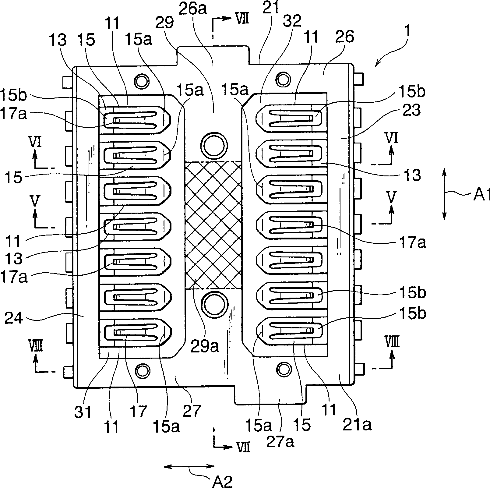
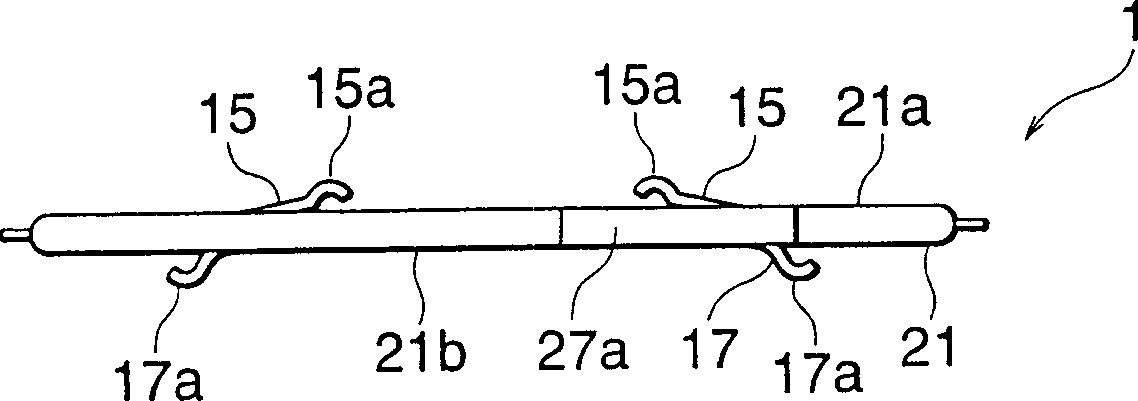
[0053] according to Figure 1-20 , first, the connector according to the first embodiment of the present invention will be described.

[0054] The connector described by numeral 1 in the figure includes: a plurality of conductive contacts 11 and an insulator 21 holding the contacts 11 . The contacts 11 are arranged in two rows along the first direction A1 ( figure 1 in the upper-lower direction on the drawing), and in the second direction A2 ( figure 1 in the horizontal direction on the drawing) opposite to each other. In each row, there are seven contact pieces 11 arranged in parallel along the first direction A1 , leaving a space between each contact piece.

[0055] Each contact 11 has a holding portion 13 (see Figure 4 and Figure 5 ), which is held by the insulator 21; the first spring part 15, which extends from one side of the holding part 13 in one direction (ie, pointing or azimuth); the second spring part 17, which extends from the middle part of the first sprin...


PUM


Abstract

In a connector (1) for connecting first and second connection objects faced to each other, a conductive contact (11) includes a holding portion (13) held by an insulator (21), a first spring portion (15), and a second spring portion (17) connected to the first spring portion. The first spring portion extends from the holding portion in one direction and has a first contacting portion to be connected to the first connection object. The second spring portion extends in the other direction opposite to the one direction and has a free end provided with a second contacting portion to be connected to the second connection object.

Description

[0001] This application claims priority from Japanese Patent Application Nos. JP2004-161644 and JP2004-296616, the disclosures of which are hereby incorporated by reference. Background technique [0002] The present invention relates to a connector for electrically connecting connecting objects such as printed circuit boards and flexible printed circuit boards (FPC). [0003] As this type of connector, Japanese Unexamined Patent Application Publication No. (JP-A) No. H11-339907 discloses a connector for connecting two printed circuit boards facing each other. The connector includes: an elastic contact member having a fixing portion fixedly connected to the housing, and one and another branching portions branched from one end of the fixing portion. The one and other branch portions are arranged in the opening portion of the case, and drawn out to one and the other surface of the case, respectively. [0004] In this connector, one and the other branch portion of a contact porti...

Claims


Application Information

Patent Timeline
IPC IPC(8): H01R12/52H01R12/55H01R13/629
Inventor 宫本邦一佐藤一臣茨木和昭樋口真佐央内藤丈晴
Owner JAPAN AVIATION ELECTRONICS IND LTD
Learn More