Cross-seat track beam support

A straddle track and seat plate technology, applied in bridges, bridge parts, bridge construction, etc., can solve the problems affecting the operation safety, service life, installation and construction convenience, material performance control, and surface treatment of straddle monorail traffic The requirements for processing precision of parts and parts are high, and the vertical height cannot be adjusted steplessly continuously, so as to achieve the effects of improving safety, reliability, installation and construction, improving convenience, and low tensile function

Pending Publication Date: 2018-01-30
CHINA RAILWAY SIYUAN SURVEY & DESIGN GRP +1
View PDF9 Cites 0 Cited by
  • Summary
  • Abstract
  • Description
  • Claims
  • Application Information

AI Technical Summary

Problems solved by technology

[0006] 1) The main force transmission part of the support is line contact (such as the hinge shaft and the cam part), which is not conducive to the overall force uniformity of the support structure
[0007] 2) The upper and lower hems of the support are rigidly connected with the upper beam body and the lower pier. When the support is damaged, it is difficult to replace it, and the support installation needs to be completed at the same time when the beam is made, and the process requirements are high.
[0008] 3) The support adopts backing plate height adjustment, so the vertical height cannot be adjusted steplessly and continuously
[0009] 4) Each component of the support is a "steel-steel" line contact friction pair, which has poor vibration damping effect, high requirements for the comprehensive performance of the contact part material, and high requirements for material performance control, surface treatment and component processing accuracy
[0010] Due to the above-mentioned many defects in the application of the existing PC track beam cast steel bearings, it affects the safety, service life, installation and maintenance convenience of the straddle monorail traffic.

Method used


Image

  • Cross-seat track beam support
  • Cross-seat track beam support
  • Cross-seat track beam support

Examples


Embodiment 1

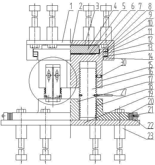
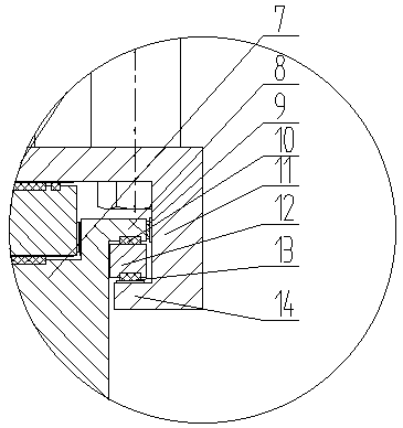
[0065] Such as Figure 7 As shown, the lower part of the lug 8 of the lower seat plate of the pull-out-resistant structure is provided with a concave arc-shaped structure. The surface of the arc structure is covered with a friction plate with a low coefficient of friction and matches with the upward convex arc surface of the rotary slider 12 to form a rotary friction pair of the rotary slider to adapt to the longitudinal rotation of the upper beam.

[0066] The lower plane of the rotating slider 12 of the anti-drawing structure is coated with a friction plate with a low friction coefficient and matched with the stainless steel sliding plate coated on the upper surface of the upper seat plate tensile plate 14 to form a plane friction pair of the rotating slider. To accommodate the longitudinal displacement of the upper beam body.

Embodiment 2

[0068] Such as Figure 8As shown, the lower part of the lug 8 of the lower seat plate of the pullout-resistant structure is provided with a convex arc-shaped structure. The surface of the arc structure is covered with a friction plate with a low coefficient of friction and matches the upper concave arc surface of the rotary slider 12 to form a rotary friction pair of the rotary slider to adapt to the longitudinal rotation of the upper beam.

[0069] The lower plane of the rotating slider 12 of the anti-drawing structure is coated with a friction plate with a low friction coefficient and matched with the stainless steel sliding plate coated on the upper surface of the upper seat plate tensile plate 14 to form a plane friction pair of the rotating slider. To accommodate the longitudinal displacement of the upper beam body.

Embodiment 3

[0071] Such as Figure 9 As shown, the lower part of the rotating slider 12 of the anti-pullout structure is provided with a convex arc-shaped structure. The surface of the arc-shaped structure is covered with a friction plate with a low coefficient of friction and matches the upper concave arc surface of the upper seat plate tensile plate 14 to form a rotating friction pair of the rotating slider to adapt to the longitudinal rotation of the upper beam.

[0072] The lower surface of the lug 8 of the lower seat plate of the anti-drawing structure is covered with a friction plate with a low friction coefficient and matches with the stainless steel slide plate coated on the upper surface of the rotating slider 12 to form a plane friction pair of the rotating slider. To accommodate the longitudinal displacement of the upper beam body.


PUM


Abstract

A cross-seat track beam support comprises an upper seat plate, a middle seat plate, a lower seat plate, at least one stepless heightening structure and base plate and drawing resisting structures arranged at two ends of the upper seat plate and the lower seat plate. The lower surface of the upper seat plate and the upper surface of the middle seat plate are planes in sliding fitness, the lower surface of the middle seat plate and the upper surface of the lower seat plate are curved surfaces in longitudinal rotating fitness, the lower seat plate is arranged on the base plate through the stepless heightening structures, each drawing resisting structure comprises an upper-seat-plate guiding plate, an upper-seat-plate drawing resisting plate and a lower-seat-plate lug, the lower-seat-plate lugis arranged in a space enclosed by the upper-seat-plate guiding plate and the upper-seat-plate drawing resisting plate, and a rotating slider is arranged between the lower-seat-plate lug and the upper-seat-plate drawing plate. By the arrangement, low-friction sliding, stepless heightening and replaceable functions of a support are realized, safety reliability of structural force and convenience in construction maintenance of the support can be effectively improved, and requirements of a cross-seat monorail traffic track beam on safety operation and construction convenience of the support aremet.

Description

technical field [0001] The invention belongs to the technical field of bridge structures or buildings, and relates to a straddle type track beam support. Background technique [0002] Straddle-type monorail traffic is a new form of modern urban rapid rail three-dimensional traffic, with low noise, strong climbing ability, small turning radius, fast and convenient, less land occupation, low cost, not restricted by terrain, and conducive to environmental protection, etc. Many advantages are a new trend in the development of urban rail transit in the future. [0003] As a two-way flexural member, the straddle-type monorail traffic track beam not only bears the vertical load and horizontal load (centrifugal force, wind force, etc.) of the train, but also bears a large torsional load, and also serves as a track for the train. As an important part of the straddle monorail traffic track beam, the straddle type track beam support is the key to ensure the normal function of the stra...

Claims


Application Information

Patent Timeline
Patent Type & Authority Applications(China)
IPC IPC(8): E01D19/04
Inventor 刘斌杨卫锋文望青宋建平彭华春朱海刘阳明顾海龙李靖韩家山余晓燕曹翁恺洪沁烨郑娜
Owner CHINA RAILWAY SIYUAN SURVEY & DESIGN GRP
Why Eureka
Try Eureka