Self-switching gripper arm structure using handling robot in narrow environment

A handling robot and self-switching technology, applied in the field of handling robots, can solve the problems of high cost, unsuitable for narrow environments, and large space for fixture arm installation, so as to achieve the effect of accuracy

Active Publication Date: 2022-01-18
河南工学院
View PDF10 Cites 0 Cited by
  • Summary
  • Abstract
  • Description
  • Claims
  • Application Information

AI Technical Summary

Problems solved by technology

[0008] The purpose of the present invention is to provide a self-switching clamp arm structure using a handling robot in a narrow environment, to solve the problem that the existing clamping arm is mostly realized by setting a plurality of clamping arms on a rotating disk in order to realize the switching of the clamping arm. It needs to be driven by a motor when switching fixtures, and the cost is high, and the installation of multiple fixture arms at the same time takes up a lot of space, which is not suitable for narrow environments

Method used


Image

  • Self-switching gripper arm structure using handling robot in narrow environment
  • Self-switching gripper arm structure using handling robot in narrow environment
  • Self-switching gripper arm structure using handling robot in narrow environment

Examples


Embodiment 1

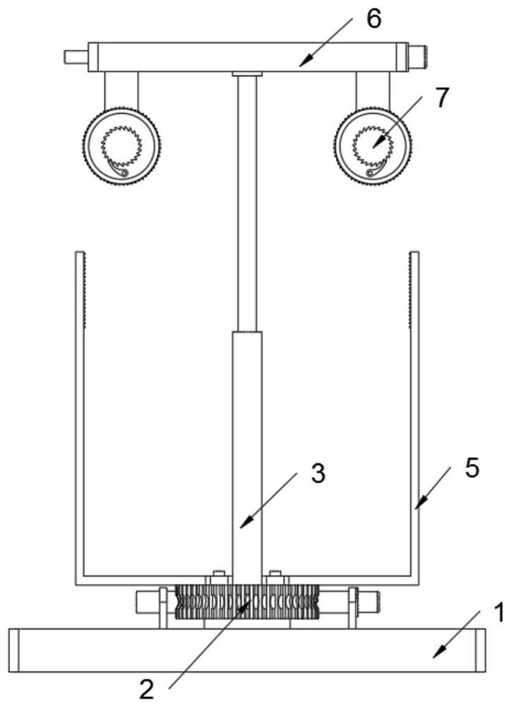
[0031] Such as Figure 1 to Figure 7As shown, the narrow environment of the preferred embodiment of the present invention uses the self-switching clamp arm structure of the handling robot, including a base 1, a rotation adjustment structure 2 is installed on the base 1, and an electric telescopic rod 3 is installed on the rotation adjustment structure 2. Rod 4 and adjusting arm 5. A clamping structure 6 is installed on the head ends of the electric telescopic rod 3 and the telescopic rod 4 , and two driving structures 7 are mounted on the clamping structure 6 . refer to Figure 6 and Figure 7 , the adjusting arm 5 includes a tooth row 501, and there are two adjusting arms 5, and the two adjusting arms 5 are symmetrically fixedly connected to the gear 201, and each adjusting arm 5 is welded with a tooth row 501; when the electric telescopic rod 3 shrinks and drives the driving structure 7 to move downwards, the gear sleeve 702 meshes with the gear row 501, and at this time ...

Embodiment 2

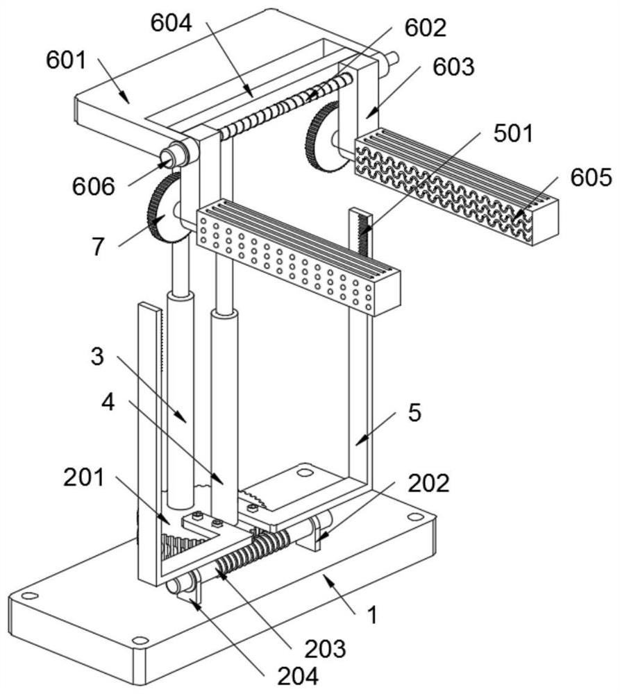
[0033] Such as figure 2 As shown, the rotation adjustment structure 2 includes a gear 201, a rotation connection seat 202, an adjustment rod A203 and a drive motor A204. The gear 201 is rotatably connected to the base 1, and the rotation connection seat 202 is welded on the base 1, and A driving motor A204 is installed. The adjusting rod A203 is rotatably connected to the rotating connection base 202, and the head end of the adjusting rod A203 is connected to the rotating shaft of the driving motor A204. The adjustment rod A203 is provided with helical teeth, and the helical teeth mesh with the gear 201, and the adjustment rod A203 and the gear 201 together form a worm gear structure, thereby realizing the rotation adjustment of the gear 201 and the automatic locking after adjustment.

[0034] Such as figure 2 As shown, the clamping structure 6 includes a main body seat 601, an adjustment rod B602 and a connecting block 603. The bottom surface of the main body seat 601 is ...

Embodiment 3

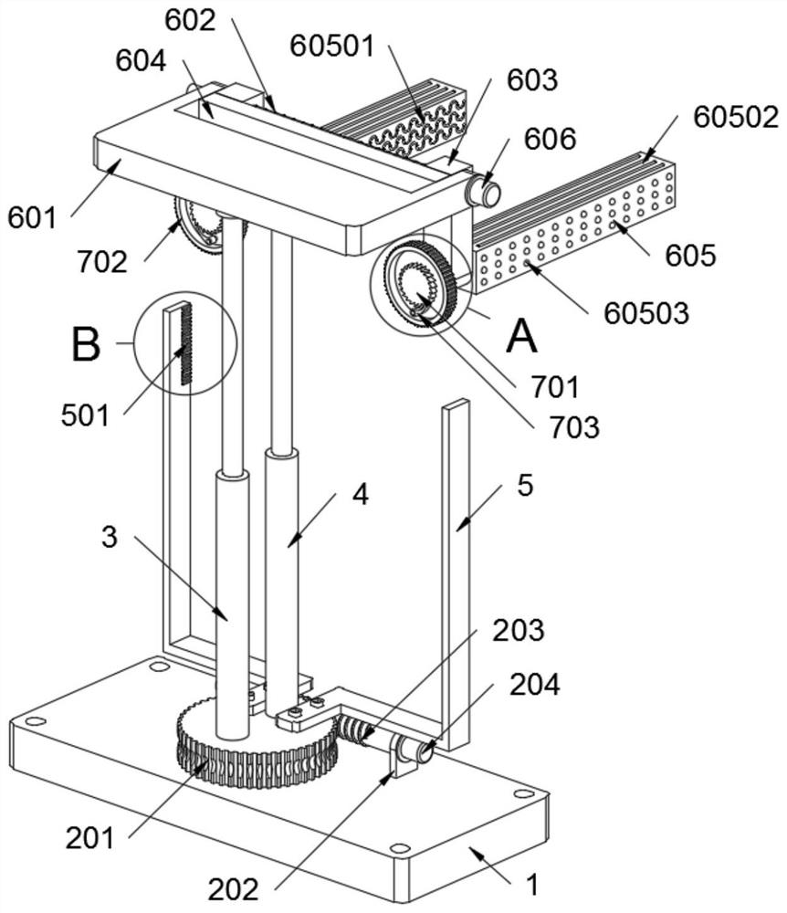
[0039] Such as image 3 and Figure 4 As shown, the driving structure 7 includes a ratchet gear 701, a gear sleeve 702 and a toggle lever 703. The ratchet gear 701 is welded on the rotating shaft of the clamping arm 605, and a gear sleeve 702 is rotatably connected to the rotating shaft of the clamping arm 605. A toggle lever 703 is installed in the gear sleeve 702, and the toggle lever 703 is meshed with the ratchet gear 701, and the ratchet gear 701, the gear sleeve 702 and the toggle lever 703 together form a ratchet structure, so that the gripping arm 605 can be realized One-way rotation.

[0040] Such as Figure 7 As shown, there is an interference rotational fit between the rotating shaft of the clamping arm 605 and the main body seat 601, and the rotational frictional resistance between the rotating shaft of the clamping arm 605 and the main body seat 601 is greater than that between the gear sleeve 702 and the rotating shaft and The sum of the frictional resistance ...


PUM


Abstract

The invention provides a self-switching fixture arm structure for a handling robot used in a narrow environment, including a base; a rotation adjustment structure is installed on the base, and an electric telescopic rod, a telescopic rod and an adjustment arm are installed on the rotation adjustment structure; the electric telescopic rod A clamping structure is installed on the head end of the telescopic rod, and two driving structures are installed on the clamping structure; the adjustment arm includes a gear row, and the two adjustment arms are symmetrically fixedly connected to the gear, and each adjustment arm is welded with a gear row ;When the electric telescopic rod shrinks and drives the driving structure to move downward, the gear sleeve and the gear row mesh, and at this time the clamping arm is in a rotating state; the two driving structures are set in mirror images, and when the gear sleeve and the gear row on the driving structure After the meshing is completed, the adjustment arm rotates at an angle of 90 degrees. In the narrow environment of the present invention, the self-switching fixture arm structure of the handling robot is used to realize the problem of self-switching of various fixture arms without using a motor drive, and realizes the accuracy of adjusting the arm switching.

Description

technical field [0001] The invention belongs to the technical field of handling robots, and more specifically relates to a self-switching clamp arm structure for handling robots used in narrow environments. Background technique [0002] With the continuous development of industrial automation, mechanical clamping arms are widely used. In various industrial production fields, mechanical clamping arms are often used to clamp objects, which not only reduces labor intensity, but also greatly improves production efficiency. Now Most of the mechanical clamping arms have complex structures and expensive manufacturing costs. [0003] For example, patent CN201711424431.0 discloses a mechanical clamping arm, including a fixed plate, a slider, a connecting rod, a spring, a first clamping piece and a second clamping piece, in the middle of the fixed plate and along the fixed A bar-shaped hole is provided in the direction of the plate length, the slider is clamped in the bar-shaped hole...

Claims


Application Information

Patent Timeline
Patent Type & Authority Patents(China)
IPC IPC(8): B25J11/00
CPCB25J11/00
Inventor 刁修慧王鹏飞焦芳敏陈韵胡新颖
Owner 河南工学院
Why Eureka
Try Eureka