Braking device for vehicle

a technology for braking devices and vehicles, applied in the direction of braking systems, etc., can solve the problem of not restricting cbs

Inactive Publication Date: 2007-04-05
HONDA MOTOR CO LTD
View PDF9 Cites 23 Cited by
  • Summary
  • Abstract
  • Description
  • Claims
  • Application Information

AI Technical Summary

Benefits of technology

[0008] To this end, an object of the present invention is to provide a braking device for a vehicle, which is capable of switching properly between single braking for one of front and rear wheels and CBS-based combined braking according to the condition of a road surface.

Problems solved by technology

Moreover, this type of braking device is also contrived so that, when the brake operating section for one of the front and rear wheels is operated, the device cuts off the supply of hydraulic pressure to the wheel braking section for the other wheel, and changes the distribution ratio according to a brake internal pressure, instead of constantly distributing a hydraulic pressure between the front and rear wheel braking sections at a fixed ratio.
Thus, for example, when driving for recreational purposes, such as sports driving, it is conceivable that the use of the brake to attempt to exert a braking force on the rear wheel alone can cause a situation where activation of the CBS is not restricted, and that the braking force acts on the front wheel.

Method used


Image

  • Braking device for vehicle
  • Braking device for vehicle
  • Braking device for vehicle

Examples


first embodiment

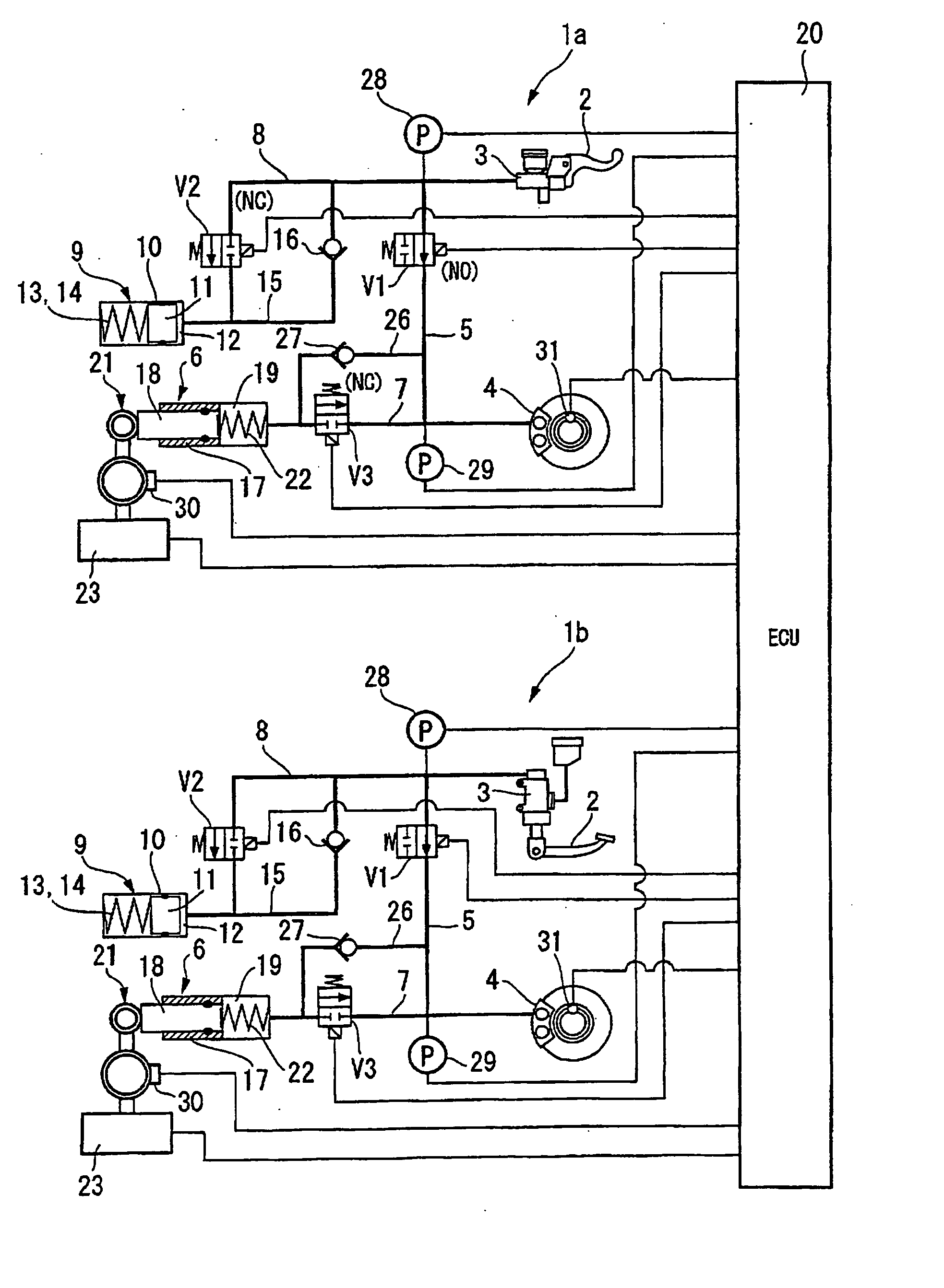
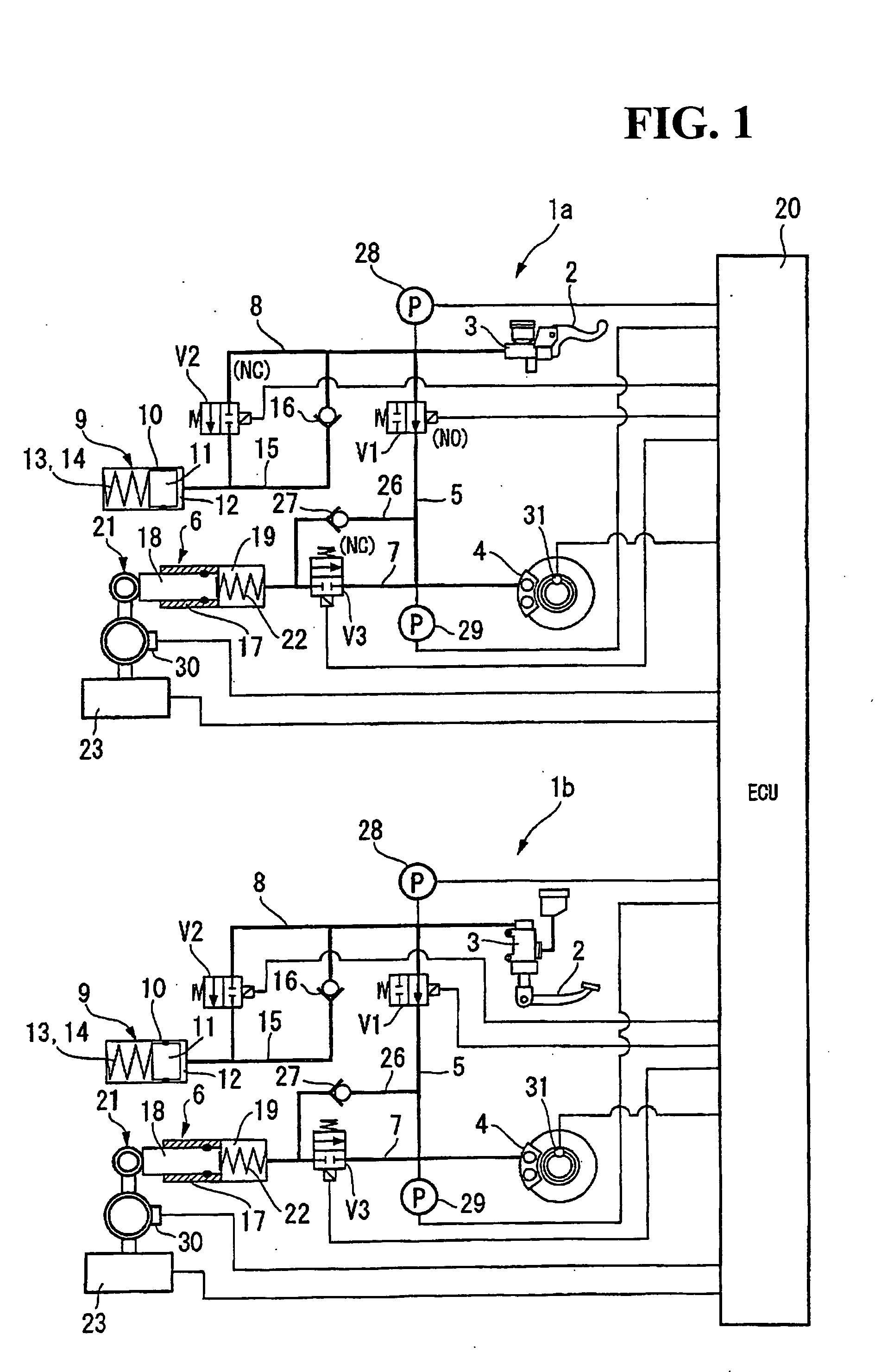
[0033]FIG. 1 shows a hydraulic circuit diagram of a braking device for a vehicle according to the present invention. This embodiment is the braking device according to the present invention as applied to a motorcycle. The braking device includes front and rear brake circuits 1a and 1b, which are independent of each other, and each of which is subject to control by a controller (ECU) 20.

[0034] In a case of this braking device, the front and rear brake circuits1a and 1b are configured to respectively use a brake lever and a brake pedal, which are brake operating sections 2 and 2, for their respective brake operations. Except for this respect, the basic configuration of the front brake circuit 1a is substantially identical to that of the rear brake circuit 1b. For this reason, the detailed descriptions will hereinbelow be given only for the rear brake circuit 1b. As for the front brake circuit 1a, the identical parts thereof as those of the rear brake circuit 1b are designated by the s...

second embodiment

[0071] In the case of a second embodiment shown in FIG. 6, braking characteristics (hydraulic pressure characteristics) during the combined braking for the front wheel are varied depending on the resistance of the road surface being high or low. Accordingly, effective combined braking can always be achieved according to the conditions of the road surface.

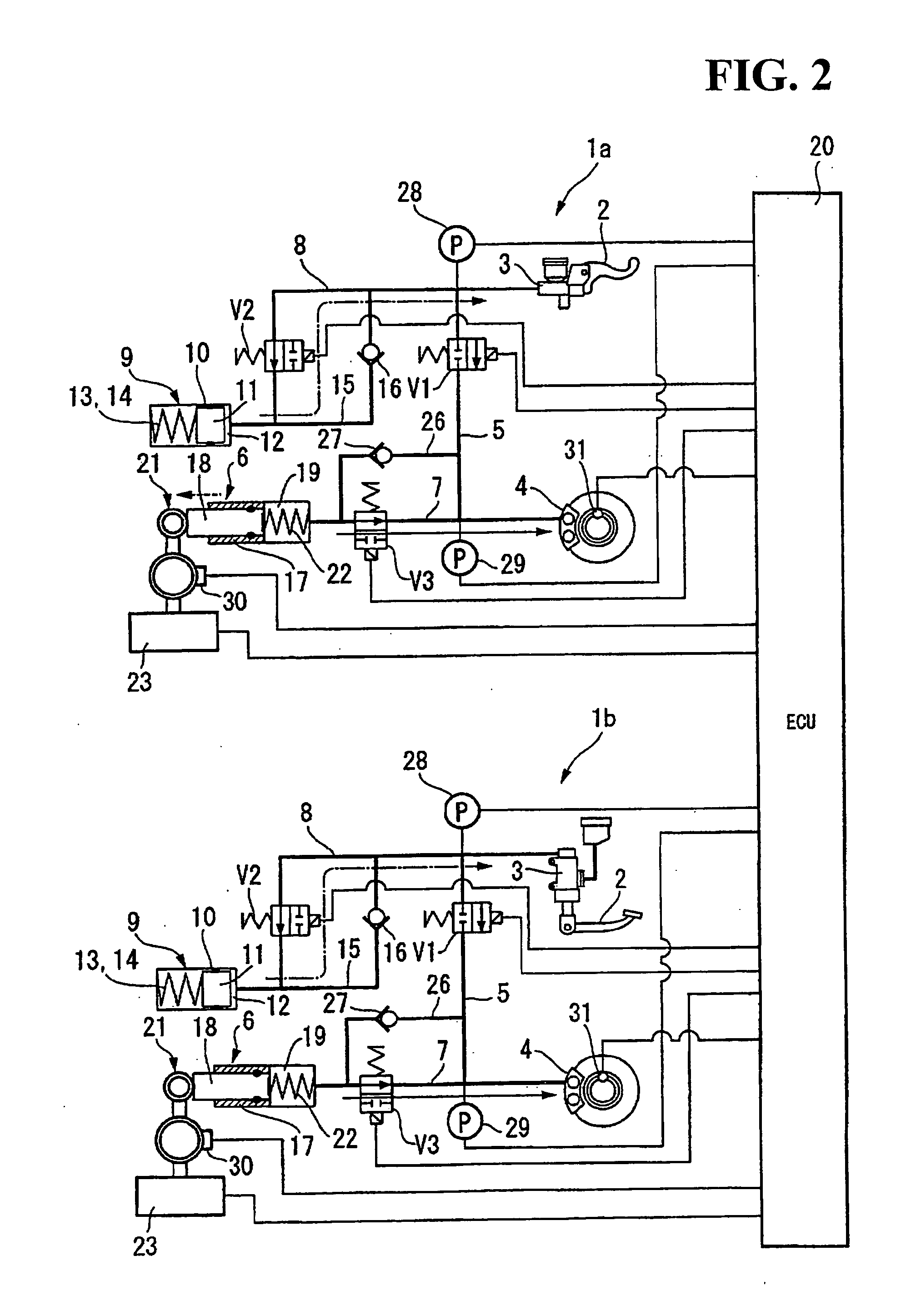
[0072] In addition, during the normal driving of the vehicle, the braking device described above closes the first solenoid on-off valve V1, and opens the second and third solenoid on-off valves V2 and V3 as shown in FIG. 2. Thereby, the bi-wire system is used (by disconnecting the brake master cylinder 3 from the brake caliper assembly 4) for braking. As opposed to the foregoing, during the normal driving, the braking device may open the first solenoid on-off valve V1, and close the second and third solenoid on-off valves V2 and V3 as shown in FIG. 1 so as to exert a pressure in the brake master cylinder 3 directly on the brake cali...

third embodiment

[0075] Moreover, the braking device does not need currents for holding the solenoid on-off valves V1 to V3 during normal braking or when braking is not activated. Thus, the corresponding amount of further reduction in power consumption is made possible. This is because the normally-open type valve is used as the first solenoid on-off valve V1, and because the normally-closed type valves are used as the second and third solenoid on-off valves V2 and V3.

[0076] The present invention is not limited to the above embodiments, and various design changes may be made to the invention without departing from the spirit and scope of the invention. For example, the descriptions have been given above for the embodiment as applied to the motorcycle using the bi-wire system and the ABS. However, the present invention may also be applied to the motorcycle which does not use the bi-wire system or the ABS. Moreover, the descriptions have been given above for the braking device which starts the combin...


PUM


Abstract

To provide a braking device for a vehicle, which is capable of switching properly between single braking for one of front and rear wheels and combined braking with CBS according to the driving conditions of the vehicle, and of thereby achieving the balance between active vehicle controllability based on a driver's intention and braking performance. Brake systems respectively for the front and rear wheels are provided so that brake caliper assemblies respectively for the front and rear wheels can be operated independently of each other with brake operating sections exclusively for the brake caliper assemblies for the front and rear wheels, respectively. The brake system for the front wheel is provided with a hydraulic pressure modulator capable of feeding a braking force to the brake caliper assembly for the front wheel. When a rear wheel slip ratio exceeds a threshold value under rear brake operation, a controller activates the hydraulic pressure modulator for the front wheel to start braking the front wheel.

Description

CROSS-REFERENCE TO RELATED APPLICATIONS [0001] This nonprovisional application claims priority under 35 U.S.C. §119(a) on Patent Application No. 2005-288333, filed in Japan on Sep. 30, 2005, the entirety of which is incorporated herein by reference. BACKGROUND OF THE INVENTION [0002] 1. Field of the Invention [0003] The present invention relates to a braking device used in a vehicle such as a motorcycle. [0004] 2. Description of Background Art [0005] A braking device for a motorcycle is known in the background art. In particular, a known braking device uses a brake system (a combined brake system, which will hereinafter be referred to simply as a “CBS”), which includes front and rear brake operating sections respectively for front and rear wheels, and front and rear wheel braking sections (e.g., brake caliper assemblies) respectively for the front and rear wheels. The brake operating section for one of the front and rear wheels is combined with the wheel braking section for the othe...

Claims


Application Information

Patent Timeline
Patent Type & Authority Applications(United States)
IPC IPC(8): B60T8/60
CPCB60T8/1706
Inventor NAKAYAMA, MASANOBUNISHIMOTO, YUKIMASA
Owner HONDA MOTOR CO LTD
Why Eureka
Try Eureka