
Biped walking mobile system, its walk controller, and walk control method therefor

a mobile system and mobile technology, applied in the field of biped walking mobile system, can solve the problems of increasing energy consumption in general, complex control regulation with more joint portions, and remarkably restricted free gait formation, and achieve the effect of improving walk stability

Inactive Publication Date: 2006-01-31
JAPAN SCI & TECH CORP
View PDF20 Cites 23 Cited by
  • Summary
  • Abstract
  • Description
  • Claims
  • Application Information

AI Technical Summary

Benefits of technology

[0009]It is the object of the present invention, taking into consideration the problems mentioned above, to provide a biped walking mobile system, its walk controller, and walk control method therefor to enhance walk stability.
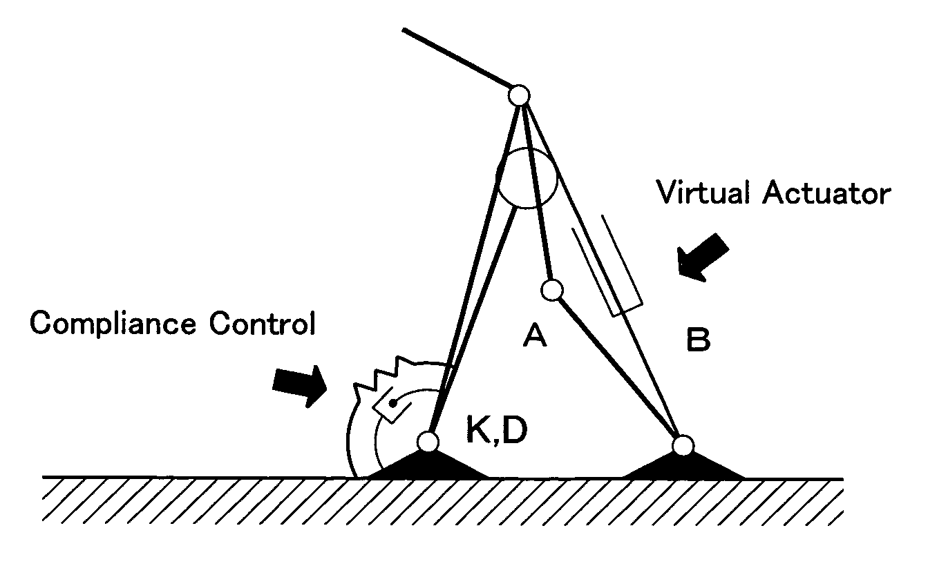
[0016]In accordance with the above-described aspect, a walk controller forms a gait data corresponding to the targeted motion, and drive-controls the drive means based on said gait data. In this case, since the walk controller drive-controls a drive means while properly switching drive and passive modes, the joint portions drive-controlled by the drive means by drive mode act as drive joints, while the joint portions drive-controlled by the drive means by passive mode act as passive joints. Thus, since the same joint portion acts as a drive or the passive joint drive-controlled by either drive or passive mode, the drive means is drive-controlled usually by drive mode, and drive-controlled by passive mode when necessary for the joint portions of, for example, knee and foot portions, upon walking of a biped walking mobile system, whereby only the merits of the drive and the passive joints are utilized, while defects can be eliminated. Consequently, natural stability by passive joints can be introduced into walking, and ZMP is automatically converged to soles, while energy consumption is saved, and the torque is lowered. Thus, ZMP is surely converged to soles at any gaits, and the walk stability is improved for a biped walking mobile system.

Problems solved by technology

However, the drive joints had also the problem such as to increase energy consumption in general, and to make more complex control regulation with more joint portions in number, since they positively utilize the torque of actuators.
Also, there was such a problem that a free gait formation is remarkably restricted by the ZMP criterion.
However, since the passive joints are pivotally moved depending on external force such as gravity etc, it is difficult to realize a free pivotal movement, and a free walk.
Consequently, with the biped walking robot provided only with drive joints, a consumption energy of actuators to the drive joint portions is increased.
On the other hand, the walking robots provided only with passive joints have long been known as toys, but they can not walk freely, and do not have sufficient walk stability.
Although the development is also carried out of the biped walk control combining the merits of both drive and passive joints, it is simple combination of drive and passive joints, with the joint portions as drive joints always act as drive joints, whereas the joint portions as passive joints always act as passive joints, and they are not really practical.

Method used


Image

  • Biped walking mobile system, its walk controller, and walk control method therefor
  • Biped walking mobile system, its walk controller, and walk control method therefor
  • Biped walking mobile system, its walk controller, and walk control method therefor

Examples


Embodiment Construction

[0030]Hereinafter, the present invention will be described in detail with reference to suitable forms of embodiment thereof illustrated in the drawing figures.

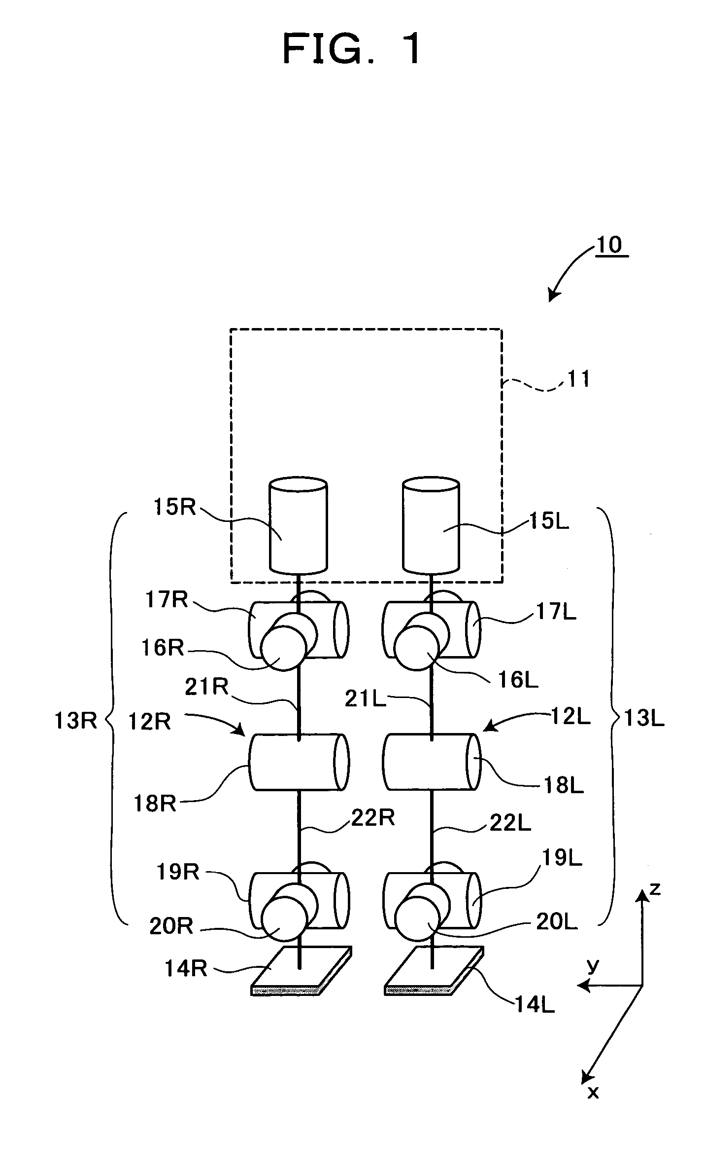
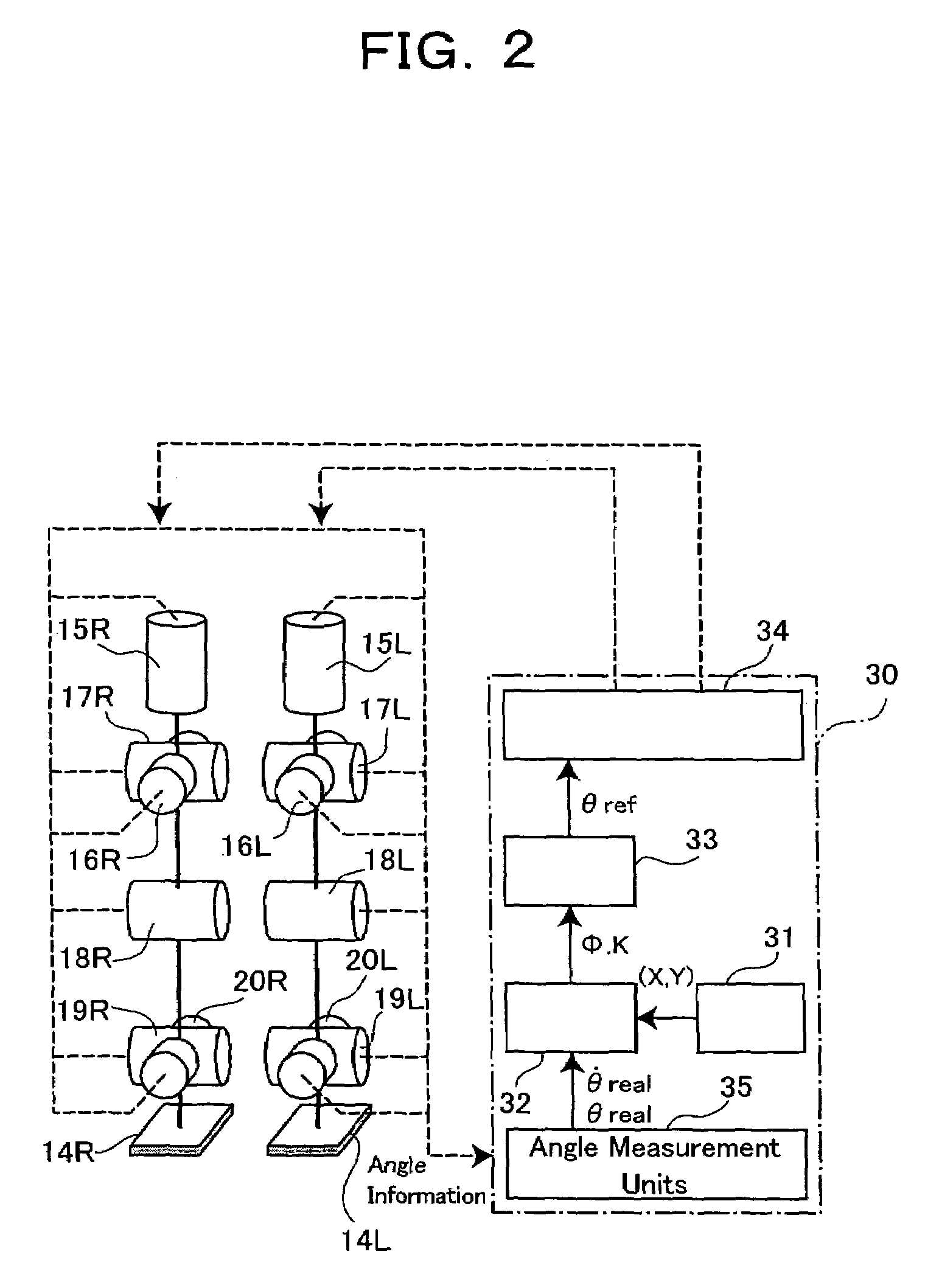
[0031]FIG. 1 and FIG. 2 show the makeup of an embodiment of a biped walking robot with a biped walking mobile system applied thereto in accordance with the present invention. Referring to FIG. 1, the biped walking robot 10 includes an upper body 11 which is a main body having at both sides of its lower part a pair of leg portions 13L and 13R attached thereto, each of the leg portions having a knee portion 12L, 12R in its midway, and a foot portion 14L, 14R at its lower end.

[0032]Here, each of the leg portions 13L, 13R has six (6) joint portions, namely in the order from above, the joint portion 15L, 15R for the leg portion rotation of a waist (around z axis) with respect to the upper body 11, joint portions 16L, 16R for the roll direction of the waist (around x axis), joint portions 17L, 17R for the pitch direction of the wais...


PUM


Abstract

The present invention provides a biped (two-footed) walking mobile system, its walk controller, and walk control method therefore, which are to realize enhancing an walk stability, as well as a consumed energy saving. A walk controller (30) of a biped walking mobile system forms a gait data by a gait forming part (33) based on parameters from a gait stabilizing part (32), and drive-controls drive means of respective joint portions (15L, 15R–20L, 20R) of each leg portion based on said gait data. In this case, the walk controller (30) is so constituted as to selectively witch a powered mode to conduct ordinary drive-control and a passive mode to drive-control the drive means similarly with passive joints, whereby drive-controlling respective joint portions. The walk controller (30) preferably switches the drive and passive modes with respect to, for example, joint portions of knee and foot portions, or switches to the powered mode for kick-up and landing during walking motion, and to the passive mode for a free foot state.

Description

TECHNICAL FIELD[0001]The present invention relates to a biped (two-footed) walking mobile system, and more specifically to its walk controller which leads to walking with both stability and low energy consumption.BACKGROUND ART[0002]A biped walking robot as it is called in the art comprises a main body having at both sides of its lower part a pair of leg portions attached thereto so as to be each pivotally movable biaxially, each of the leg portions having a knee portion in its midway and a foot portion at its lower end, the foot portions being attached to their corresponding leg portions so as to be pivotally movable biaxially, joint portions supporting the leg, knee, and foot portions for pivotally moving them, respectively, a drive means for pivotally moving the joint portions, a gait former for forming gait data in accordance with a targeted motion, and a walk controller for drive-controlling the drive means based on the gait data.[0003]In accordance with the thus constituted bi...

Claims


Application Information

Patent Timeline
Patent Type & Authority Patents(United States)
IPC IPC(8): B25J5/00G06F19/00A63H11/18B25J13/00B62D57/032
CPCB62D57/032B25J9/1641B25J13/00
Inventor FURUTA, TAKAYUKIOKUMURA, YUTAWARA, TETSUOKITANO, HIROAKI
Owner JAPAN SCI & TECH CORP
Learn More