
Filament Winding Apparatus

a technology of winding apparatus and filament, which is applied in the manufacture of inductance/transformer/magnet, chemistry apparatus and processes, layered products, etc., can solve the problems of troublesome arrangement change, wasteful consumption of fiber bundles, etc., and achieve efficient manufacturing, shortening the time necessary for winding process, and reducing the effect of tim

Active Publication Date: 2009-05-21
MURATA MASCH LTD
View PDF5 Cites 20 Cited by
  • Summary
  • Abstract
  • Description
  • Claims
  • Application Information

AI Technical Summary

Benefits of technology

[0006]The winding process can be carried out in a shorter time such that the pressure container is more efficiently manufactured by simultaneously helical winding the group of fiber bundles around the mandrel in the above manner. In this regards, the time necessary for the winding process can be reduced by increasing the number of fiber bundles wound around the mandrel by helical winding.
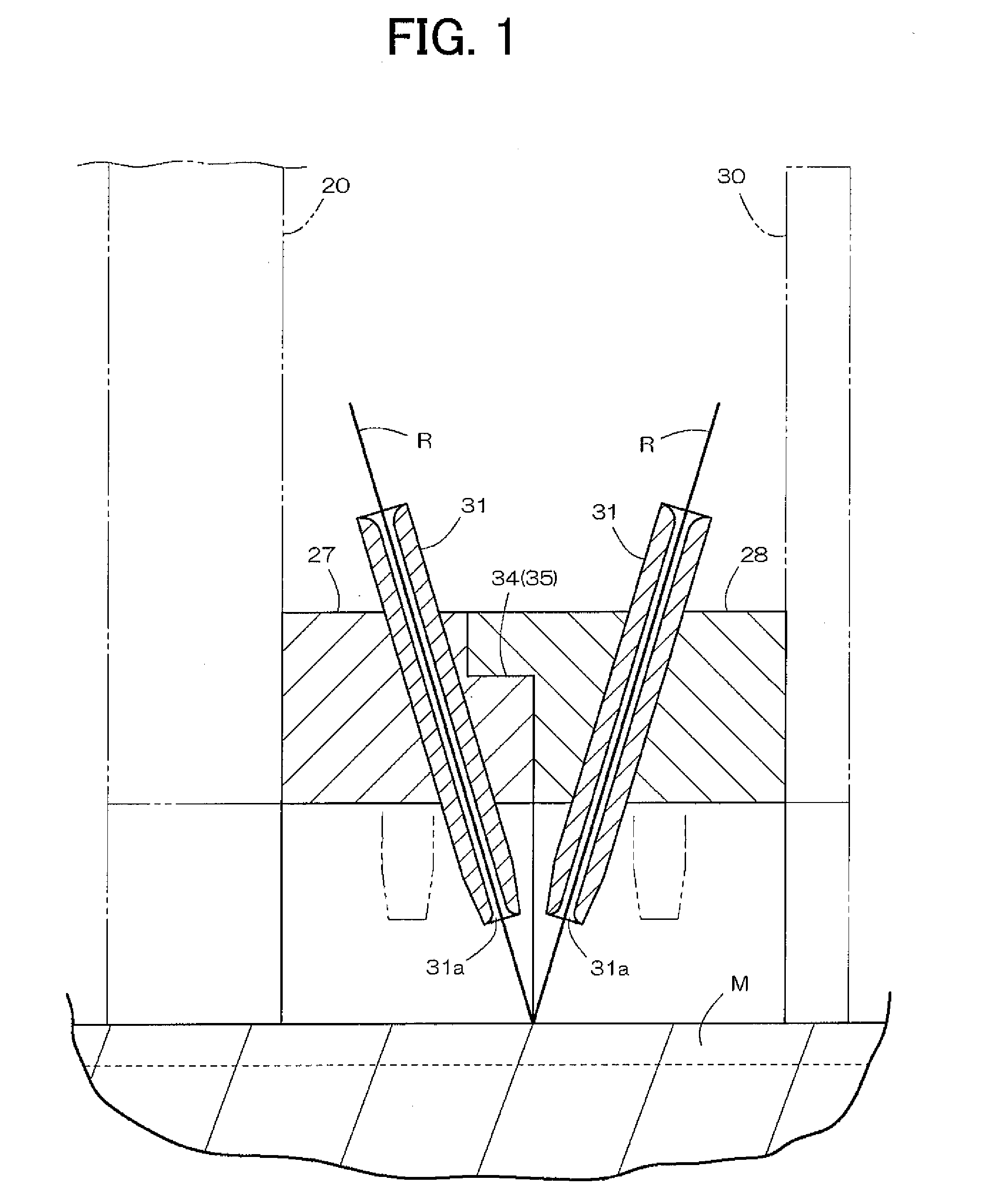
[0009]The present invention provides a filament winding apparatus including a plurality of guide rings that efficiently performs a helical winding process in which the winding angle of the fiber bundle differs, and appropriately forms a helical wound layer. The present invention also provides a filament winding apparatus that substantially matches the winding angles of a fiber bundle R supplied from a guide tube attached to each guide ring even if the winding angle of the fiber bundle R is large, and appropriately and efficiently forms a helical wound layer.
[0014]According to the filament winding apparatus of the present invention, the number of fiber bundles R supplied from the helical winding head 21 can be changed every time the winding angle of the fiber bundle R is differed by switching the guide rings between the first and second states with the phase switching structure. Therefore, a helical winding process in which the winding angle of the fiber bundles is different can be efficiently carried out, and the helical wound layer can be appropriately formed while avoiding wasteful consumption of the fiber bundle even if the winding angle of the fiber bundle R is large. The trouble of changing the arrangement is advantageously excluded since a0. Helical winding process of different winding angles can be continuously carried out.
[0015]In the present invention, the tube exits of the guide tubes are arranged close along the axis center direction of the mandrel in the first state. Thus, the winding angle of the fiber bundle R supplied from each guide tube can be substantially matched, and the helical wound layer can be appropriately and efficiently formed even in a state where the winding angle of the fiber bundle R is large.
[0017]When the phase switching structure is configured by an operator switching one of the guide rings that can be rotatably displaced, a positioning structure arranged between the adjacent guide rings, the rotation limit of the guide ring on the movable side can be defined by the positioning structure. Therefore, the switching function by the operator and the positioning function by the positioning structure are performed individually, and the structure of the phase switching structure is simplified, but nevertheless, the guide ring can always be accurately switched.

Problems solved by technology

That is, wasteful consumption of the fiber bundle becomes inevitable.
However, it is very troublesome to change the arrangement when performing helical winding while changing the winding angle of the fiber bundle.

Method used


Image

  • Filament Winding Apparatus
  • Filament Winding Apparatus
  • Filament Winding Apparatus

Examples


example

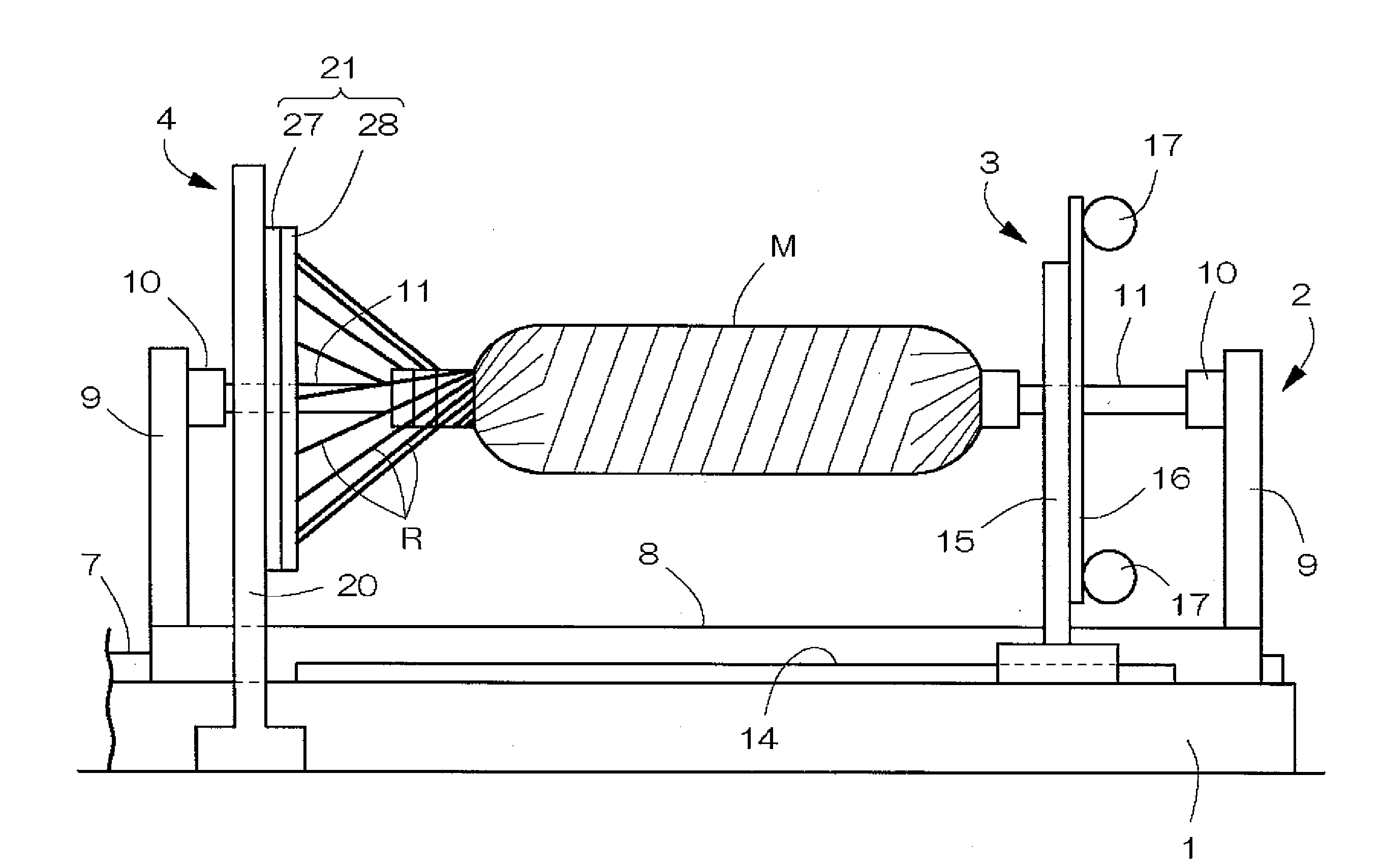
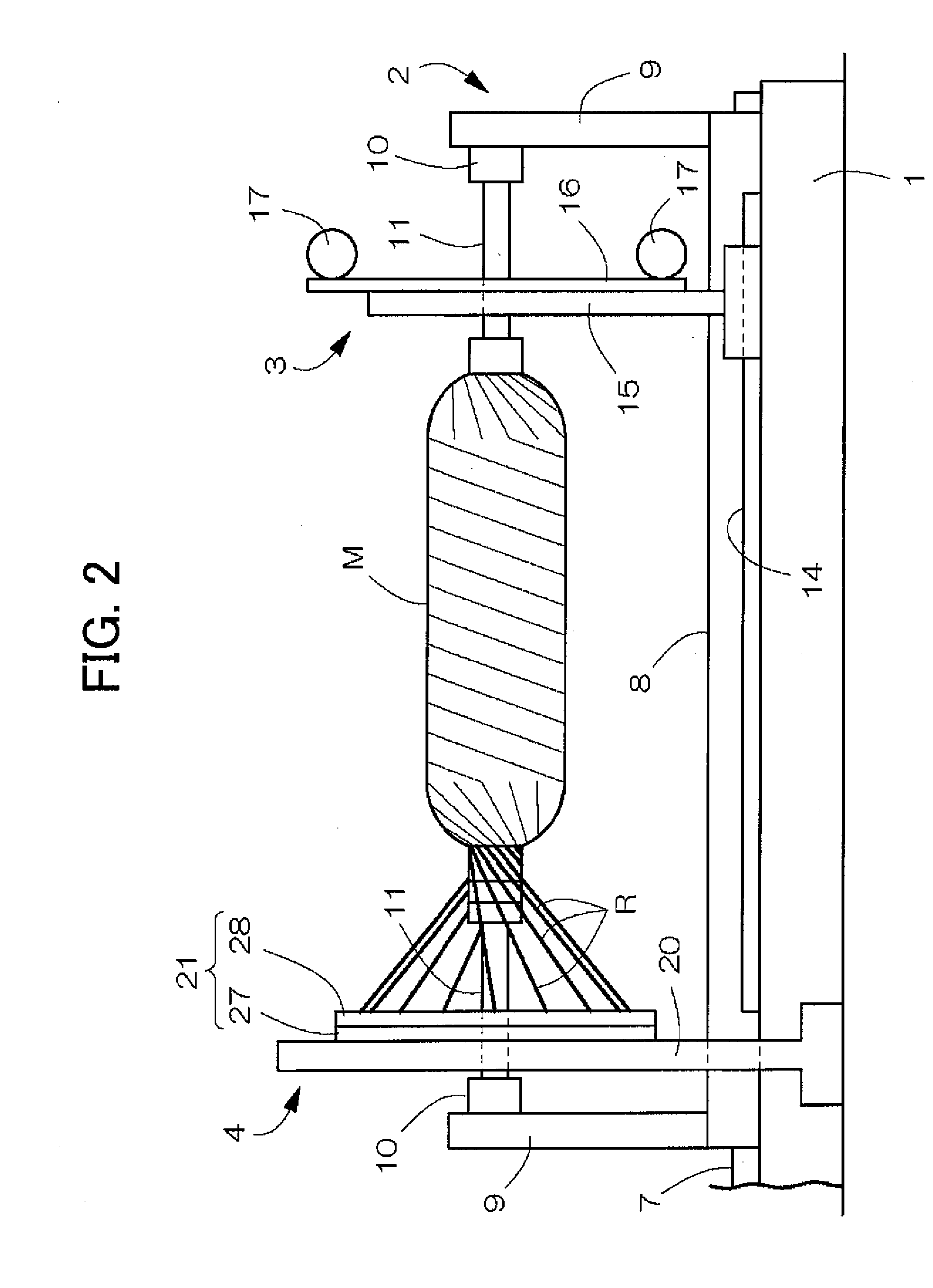
[0029]FIG. 1-8 show an example of a filament winding apparatus according to the present invention comprising a fiber bundle supply structure and a winding device. The winding device comprises a supporting board 2 that is arranged on an upper part of a mount 1 that extends lengthwise in a left and right direction and that supports a mandrel M; a hoop winding device 3; a helical winding device 4; and a mandrel replacing device. The supporting board 2 and the hoop winding device 3 are driven by a drive mechanism in a reciprocating manner along a longitudinal direction of the mount 1. The helical winding device 4 is fixed at a central position of the mount 1, and feeds and guides a fiber bundle R from a group of creels supported by the fiber bundle supply structure to the mandrel M.

[0030]Where the final product is a pressure container, the mandrel M includes a metal container made of high strength aluminum material, stainless material, or the like. The mandrel M may alternatively be a p...


PUM

PropertyMeasurementUnit
Angleaaaaaaaaaa

Abstract

A filament winding apparatus efficiently performs a helical winding process in which the winding angle of the fiber bundle differs. A helical winding head includes two guide rings, adjacently arranged along an axis center of the mandrel, and guide tubes arranged at equal intervals along a circumferential direction of the guide rings. The guide rings are switchable between a first state in which phase positions of the guide tubes are matched and a second state in which the phase positions of the guide tubes are evenly shifted in the circumferential direction by a phase switching structure. Tube exits of the guide tubes are arranged close in the first state.

Description

CROSS-REFERENCE TO RELATED APPLICATIONS[0001]This application claims the benefit of priority under 35 USC 119 of Japanese application no. 2007-298704, filed on Nov. 16, 2007, which is incorporated herein by reference.BACKGROUND OF THE INVENTION[0002]1. Field of the Invention[0003]The present invention relates to a filament winding apparatus equipped with a helical winding device.[0004]2. Description of the Related Art[0005]When forming a pressure container and the like through a filament winding method, a fiber bundle applied with resin is hoop wound or helical wound around a mandrel to form a reinforcement layer (see Japanese Laid-Open Patent Publication No. 10-119138 (paragraph 0002, FIG. 3)). A filament winding apparatus that guides numerous fiber bundles with a plurality of helical winding rings, and simultaneously winds a group of fiber bundles around the mandrel, is disclosed in Japanese Laid-Open Patent Publication No. 2004-314550 (paragraph 0019, FIG. 1). In Japanese Laid-Op...

Claims


Application Information

Patent Timeline
IPC IPC(8): B32B37/00
CPCB29C53/64B29C63/24B29C53/8016
Inventor UOZUMI, TADASHITANIGAWA, MOTOHIRO
Owner MURATA MASCH LTD
Learn More