A driving device for grinding brake discs
What is Al technical title?
Al technical title is built by PatSnap Al team. It summarizes the technical point description of the patent document.
A driving device and brake disc technology, which is applied to grinding/polishing safety devices, grinding machine parts, grinding/polishing equipment, etc., can solve the problems of unguaranteed processing quality of brake discs and difficult processing of brake discs. , to achieve the effect of saving manpower and material resources, high degree of automation, and simple structure design
Active Publication Date: 2018-03-30
ANHUI PULUN INTELLIGENT EQUIP CO LTD
View PDF7 Cites 0 Cited by
Summary
Abstract
Description
Claims
Application Information
AI Technical Summary
This helps you quickly interpret patents by identifying the three key elements:
Problems solved by technology
Method used
Benefits of technology
Problems solved by technology
In the production process of brake discs, the processing of brake discs has always been a relatively difficult problem, and the existing technology basically uses manual positioning, so the processing quality of brake discs has not been guaranteed
Method used
Image
Click on the blue label to locate the original text in one second.
Reading with bidirectional positioning of images and text.
Examples
Embodiment Construction
[0015] In order to make the purpose, technical solutions and beneficial effects of the present invention more clear, the preferred embodiments of the present invention will be described in detail below in conjunction with the accompanying drawings, and the present invention will be further described to facilitate the understanding of technical personnel.
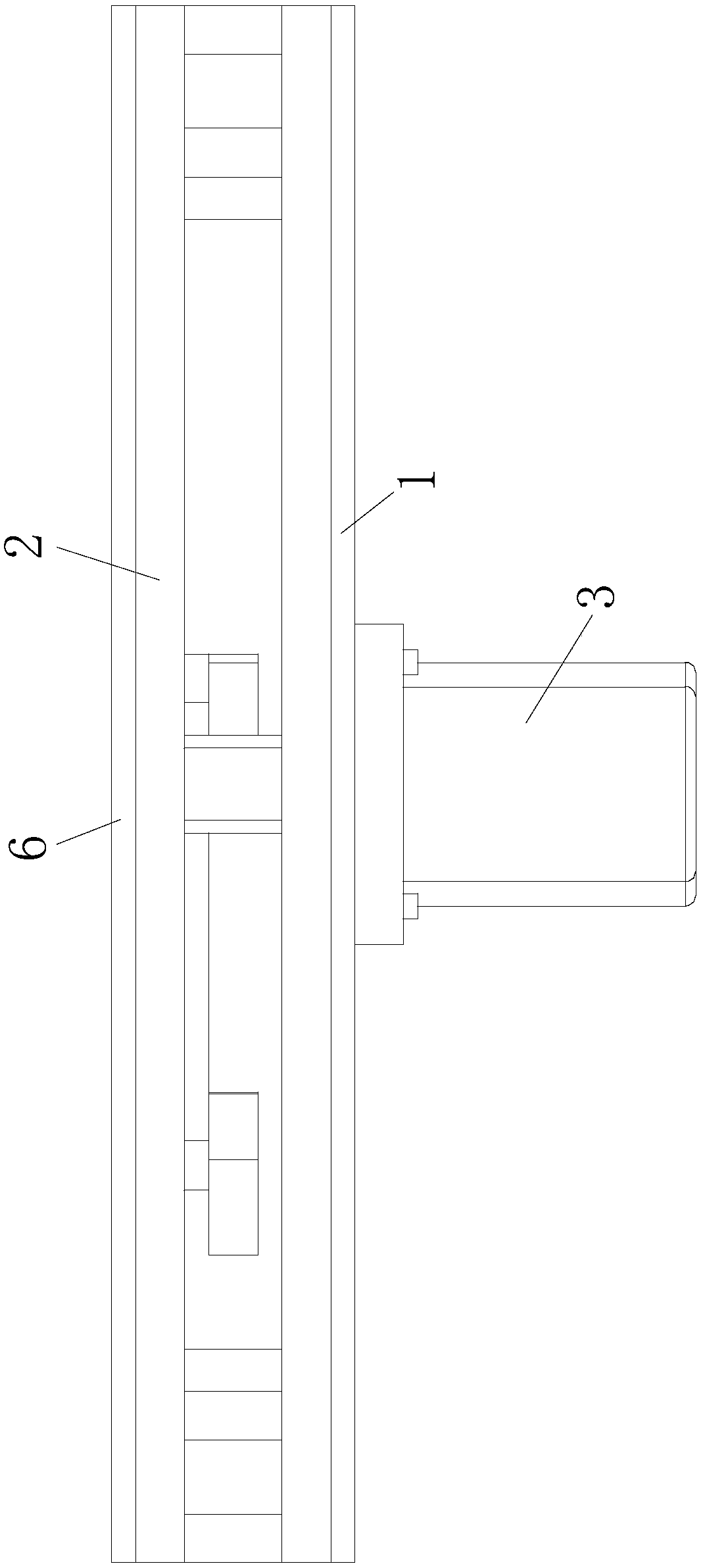
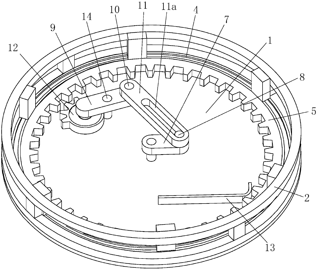
[0016] Such as Figure 1 to Figure 3 As shown, a driving device for brake disc grinding includes an upper end plate 6, a support frame 2, a motor 3, a lower end plate 1, a bearing 4, a ring gear 5, a drive plate 7, a No. 1 connecting shaft 8, a vertical shaft 14, Connecting plate 9, No. 2 connecting shaft 10, driven plate 11, driving wheel 12 and elastic flap 13, described lower end plate 1 is fixed on the lower end of support frame 2, and described motor 3 is fixed on the lower end of lower end plate 1, so The bearing 4 is fixed on the inner wall of the support frame 2, the ring gear 5 is fixed on the inner wall of the bear...
PUM
Abstract
The invention discloses a driving device used for grinding a brake disc. The driving device comprises an upper end plate, a support frame, a motor, a lower end plate, a bearing, a gear ring, a driving plate, a first connecting shaft, a vertical shaft, a connecting plate, a second connecting shaft, a driven plate, a driving wheel and an elastic dummy wafer, wherein the lower end plate is fixed at the lower end of the support frame, and the motor is fixed at the lower end of the lower end plate; the bearing is fixed to the inner wall of the support frame, and the gear ring is fixed to the inner wall of the bearing; the driving plate is fixed to a shaft of a first motor, and the first connecting shaft is fixed to the upper end of the driving plate; the vertical shaft is fixed to the upper end of the lower end plate; the connecting plate is fixed to the outer wall of the vertical shaft, and the driving wheel is fixed at the lower end of the connecting plate; and the elastic dummy wafer is fixed to the lower end plate. The driving device has the advantages of being simple in structural design, being simple to use and the like, realizes the intermittent rotation of the brake disc, utilizes the elastic dummy wafer to realize the one-directional rotation of the device, ensures the smooth grinding of the brake disc, is high in automation degree, improves the grinding efficiency of the brake disc and saves labor and materials.
Description
technical field [0001] The invention relates to the technical field of driving equipment for grinding automobile brake discs, in particular to a driving device for grinding brake discs. Background technique [0002] With the improvement of our country's consumption level, our country's auto industry has made great progress. As of 2013, there are more than 200,000 auto parts manufacturing enterprises in my country, and as many as 16,000 major auto parts manufacturing enterprises, including more than 10,000 enterprises above designated size, and more than 1,200 foreign-funded enterprises. Therefore, every enterprise must improve its own production technology in order to be competitive in the market. [0003] During the braking process of a car, the brake disc is an important part of the car brake. In the production process of the brake disc, the processing of the brake disc has always been a relatively difficult problem, and in the prior art, positioning is basically perform...
Claims
Application Information
Patent Timeline
Application Date:The date an application was filed.
Publication Date:The date a patent or application was officially published.
First Publication Date:The earliest publication date of a patent with the same application number.
Issue Date:Publication date of the patent grant document.
PCT Entry Date:The Entry date of PCT National Phase.
Estimated Expiry Date:The statutory expiry date of a patent right according to the Patent Law, and it is the longest term of protection that the patent right can achieve without the termination of the patent right due to other reasons(Term extension factor has been taken into account ).
Invalid Date:Actual expiry date is based on effective date or publication date of legal transaction data of invalid patent.