A float linkage paint brushing device

A floating and linkage technology, which is applied to devices and coatings that apply liquid to the surface, and can solve the problems of low efficiency of floating paint and uneven distribution of floating paint.

Active Publication Date: 2021-09-14
陈依琳
View PDF8 Cites 1 Cited by
  • Summary
  • Abstract
  • Description
  • Claims
  • Application Information

AI Technical Summary

Problems solved by technology

[0005] In order to solve the above-mentioned technical problems, the present invention provides a buoy-linked painting device to solve the problem that when painting a buoy, the worker needs to hold one end of the buoy, and then the worker can put the brush into the buoy with his right hand. In the paint, the brush is stained with an appropriate amount of paint. When the brush is stained with an appropriate amount of paint, the worker can push the brush back and forth to move back and forth on the float. The buoy touches, and then the brush can paint the buoy. When the worker paints the buoy, the worker needs to rotate the buoy with his left hand. The purpose of the worker's left hand rotation is to make the buoy evenly distributed with an appropriate amount of paint. It can be seen that when workers paint the buoy, they need to rotate the buoy on the left hand side. The strength of the worker's rotation of the buoy is different each time, which may lead to uneven distribution of paint on the buoy, and workers need to frequently paint the buoy. The brush is soaked in the paint, and the workers manually paint the floats with low efficiency

Method used


Image

  • A float linkage paint brushing device
  • A float linkage paint brushing device
  • A float linkage paint brushing device

Examples


Embodiment

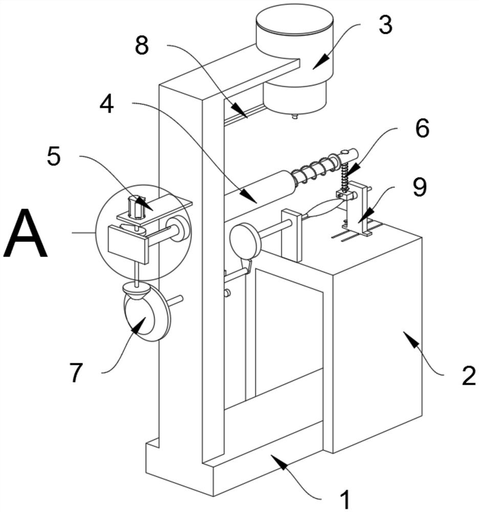
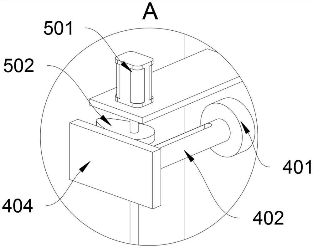
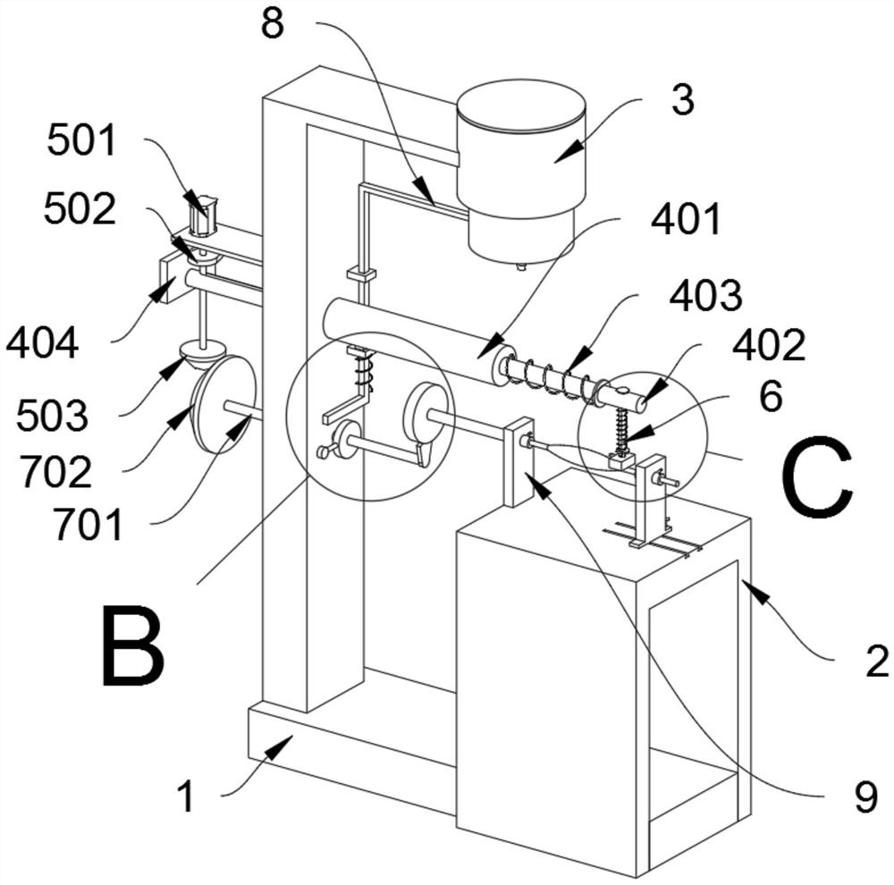
[0032] as attached figure 1 To attach Figure 8 Shown:

[0033] The invention provides a float linkage painting device, which comprises a mounting frame body 1, a fixture seat 2 is fixedly connected to the right side of the lower part of the mounting frame body 1 through bolts, the outer top of the fixture seat 2 is connected with a floating fixing seat, and the upper part of the mounting frame body 1 is provided with There is a telescopic machine structure 4, the right part of the telescopic machine structure 4 is slidingly provided with a brushing mechanism, and the upper left side of the mounting frame body 1 is provided with a driving structure 5, and the driving structure 5 cooperates with the telescopic machine structure 4, and the mounting frame body 1 The middle part is provided with a floating and rotating driving structure 7, which cooperates with the driving structure 5, and an elastic paint bucket 3 is fixedly connected to the upper right side of the mounting fram...


PUM


Abstract

The invention provides a float-linked paint brushing device, which relates to the field of paint brushing devices, and solves the problem of low overall efficiency due to the fact that paint is mostly manually dipped for multiple times, and floats need to be continuously rotated. A float-linked paint brushing device, comprising a mounting frame body; a fixture seat is fixedly connected to the mounting frame body through bolts. Through the setting of the driving structure, the buoy rotation driving structure and the extrusion structure, the bevel gear A and the bevel gear B are meshed. When the motor rotates, it can also drive the rotating rod on the buoy rotation driving structure to rotate. At this time, First, the rotating rod drives the toggle head to rotate, and the elastic paint bucket can be squeezed through the rotating extrusion structure to realize the replenishment of the paint in the brushing head; second, the rotating rod drives the incomplete gear Rotate, at this time, because the incomplete gear meshes with the gear, the intermittent rotation of the float can also be realized through the rotation of the motor.

Description

technical field [0001] The invention belongs to the technical field of painting devices, and more specifically relates to a float-linked painting device. Background technique [0002] Now most of the floats are used to close the pores and prevent the floats from bursting during use. Workers generally paint a layer of primer on the surface of the floats. [0003] At present, when the float is painted, there are mainly the following deficiencies: at present, when the float is painted, the worker needs to hold one end of the float, and the worker can put the brush into the paint with his right hand, so that all the paint on the brush Stained with a proper amount of paint, when the brush is stained with a proper amount of paint, the worker can push the brush back and forth to move back and forth on the float, and the bristles of the brush will contact the float during the forward and backward movement of the brush, so that the brush can The float is painted with primer. When th...

Claims


Application Information

Patent Timeline
Patent Type & Authority Patents(China)
IPC IPC(8): B05C1/02B05C11/10B05C13/02
CPCB05C1/02B05C11/1002B05C13/02
Inventor 陈依琳陈振全
Owner 陈依琳
Why Eureka
Try Eureka