Electric machine stator structure

A motor stator and stator technology, applied to the shape/style/structure of the winding insulation, can solve the problems of damage to the folded part, reduce the insulation performance, increase the working process, etc., and achieve the effect of reducing the force and reducing the manufacturing cost

Inactive Publication Date: 2005-12-14
LG ELECTRONICS (TIANJIN) APPLIANCES CO LTD
View PDF0 Cites 3 Cited by
  • Summary
  • Abstract
  • Description
  • Claims
  • Application Information

AI Technical Summary

Problems solved by technology

When winding the stator coil 21, under the influence of the stator coil 21, the slotted insulating paper 31 is subjected to a force in the vertical direction, causing the folded parts 35 at both ends of the slotted insulating paper 31 to be damag

Method used


Image

  • Electric machine stator structure
  • Electric machine stator structure
  • Electric machine stator structure

Examples


Example Embodiment

[0020] Hereinafter, an embodiment of the motor stator structure of the present invention will be described in detail with reference to the accompanying drawings. In the following description, the same reference numerals are used for the same components as those of the conventional structure.

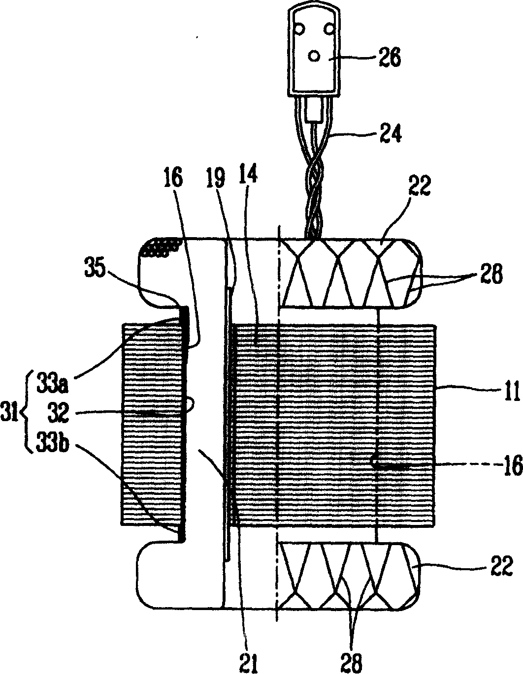
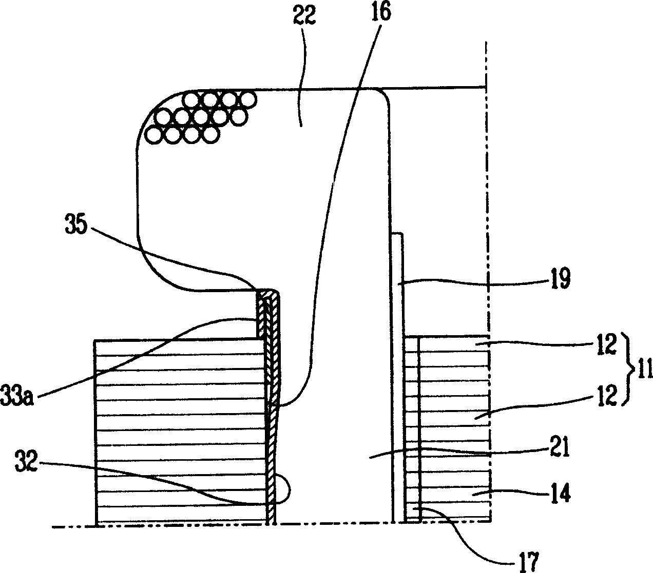
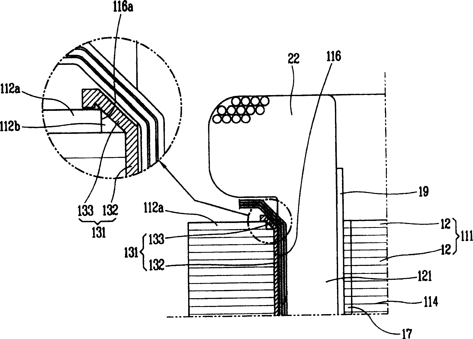
[0021] image 3 It is a cross-sectional view of an embodiment of the motor stator structure of the present invention. As shown in the figure, an embodiment of the motor fixing structure of the present invention has a stator magnetic core 111 and a stator coil 121 . A rotor hole 114 is formed in the center of the stator core 111, and the rotating shaft of the rotor can be arranged in the up-down direction (not shown). The circumference of the rotor hole 114 is open to the center to form a number of slots 116 . The stator coil 121 is wound and inserted into the slot 116 of the stator core 111 . An end wire 24 extends from the upper side of the stator coil 121 , and the end of the end w...


PUM


Abstract

The present invention relates to one kind of motor stator structure. The stator has magnetic core formed with laminated steel sheets, insulating paper set inside the slots in the magnetic core and stator coils wound on the insulating paper inside the slots. The rotatable rotor is inserted in the center of the stator magnetic core. In the stator structure, at least one of the ends of insulating paper inside the slots has bent part of certain angle to disperse the force on the coil. Correspondingly, the steel sheets for the magnetic core have larger slots to form steps to support the bent part, and paint is coated between the bent part of the insulating paper and the step of the magnetic core. The present invention can ensure the insulating performance of the insulating paper and reduce the number of parts to lower the production cost.

Description

technical field [0001] The invention relates to a motor stator structure (STATOR STRUCTURE FOR MOTOR); by improving the magnetic core structure composing the stator, the invention prevents the damage of insulating paper when winding coils, and reduces the number of parts at the same time. Background technique [0002] figure 1 A partial cross-sectional view of the stator structure of a conventional motor. figure 2 for figure 1 An enlarged cross-sectional view of important parts. [0003] As shown in the figure, the motor stator has a stator core 11 and a stator coil 21 . A rotor hole 14 is formed in the center of the stator core 11, and the rotating shaft of the rotor can be arranged in the up-down direction. The circumference of the rotor hole 14 is open to the center to form a plurality of slots 16 . The stator coil 21 is wound and inserted into the slot 16 of the stator core 11 . An end wire 24 extends from the upper side of the stator coil 21 , and the end of the ...

Claims


Application Information

Patent Timeline
IPC IPC(8): H02K3/34
Inventor 周正勋
Owner LG ELECTRONICS (TIANJIN) APPLIANCES CO LTD
Why Eureka
Try Eureka